Service notebook of Harold Gordon Cornell - 1917 - Part 10

9
Instructions To Pupils
Turning:-
The first turn after taking off, should not be made
below 200 ft. Prior to commencing the bank & turn
the nose of the machine should always be put down.
In this case with an 80 H.P. Renault, the nose would be
put down to the "Flying Level" position. Bu This takes load
off engine & accelerates speed, thereby avoiding danger
of side slip.
Having put nose down, commence to put the bank on,
and as soon as the machine begins to heel over apply
a corresponding amount of rudder, ats the bank
increases so increase the amount of rudder. Short-horns
differ in the rigging, and it will found that on l.h. turns
a machine has a tendency to put the nose down still
further, whilst on the right the machine tends to get
the nose up. Hence while turning, the pupil requires
to keep an eye on the horizon to note that the nose of
the machine is maintaining its correct position, & also
he should glance down the wing to see that his bank
is not too steep, but well in proportion to the turn
that is being executed. The pupil will notice as time
10.
Instructions to Pupils
Climbing.
goes on, that if the machine tends to put the nose down
on the left turn, that if, after having reached the
desired angle of bank, he puts on a little opposite
check (i.e. he keeps a little pressure on the controls
against further banking,) the tendency to get the nose
down will stop.
Again, when doing a right turn on the same machine,
it will be found necessary to hold the machine into the
bank, & at the same time prevent the nose of the machine
coming up. Having completed turn, take the rudder off,
& immediately after the controls taking off the bank.
Pupils should remember that though a Short-horn is
fairly sensitive fore & aft, it is sluggish laterally, and to
put the machine into a bank & more especially to
take it out requires a really firm pressure on the controls.
As soon as the machine is once more on a level keel,
the attitude that she assumes should be that of flying
hard. The pupil then brings back the control and
continues to climb at this previous climbing angle.
11.
Instructions for Pupils
Flying Level
This is not good practice for a beginner, as with the
load off the tail, the engine at once accelerates.
As this, for any length of time, will set up overheating,
with the accomp. wear & tear, it is advisable that the
pupil should always climb except when making a turn,
until having reached a considerable height, say 2000 to
2500 feet, he closes the throttle down about ¾ & glides
round until he has reached the level of 400 to 500 feet.
The reason for not closing down the throttle of the engine
completely is to avoid any undue risk of the engine
stopping altogether, caused by the varying temperatures
met with at different heights. When the pupil has
reached the desired height, with the rt. hand he puts
the control lever gently forward and with the left retards
the throttle lever until it is about ¼ open. Apart from
looking at position of throttle lever, the pupil should be
able to judge the speed of his engine by ear.
In the event of having to fly level, say owing to low
clouds, he will slightly retard the throttle until the
rev. counter does not show more than 1775 revs.
12.
Instructions to Pupils
Flying Level (cont)
Some good 80 H.P. Renaults will show 1775 to 1800 revs
on the climb, but as soon as the machine is placed
on a level keel, the revs. jump to 1900.
Gliding. It is generally advisable for a pupil to come
down at a speed not under 60 m.p.h. with the
throttle about ¼ open. As soon as he feels he is
well within the aerodrome & is not going to drop
short or overshoot the mark he means to land upon,
he must close the throttle completely. The
Landing It is only with practice that a pupil can learn
to land a machine. Suppose machine is coming
down at 60 m.p.h. - when about 30 ft. from the
ground the speed should be reduced by a very slight
backward movement of the control. When about 6 to 8.
off the ground, the machine should be brought to the
Flying Level position & held there until the pupil feels
the machine shows a tendency to sink. He then commences
to pull the control lever gently towards him, being careful
not to jerk or move the lever too rapidly. Upon taking
the ground, the pupil must at once check with the rudder
13.
Instructions to Pupils
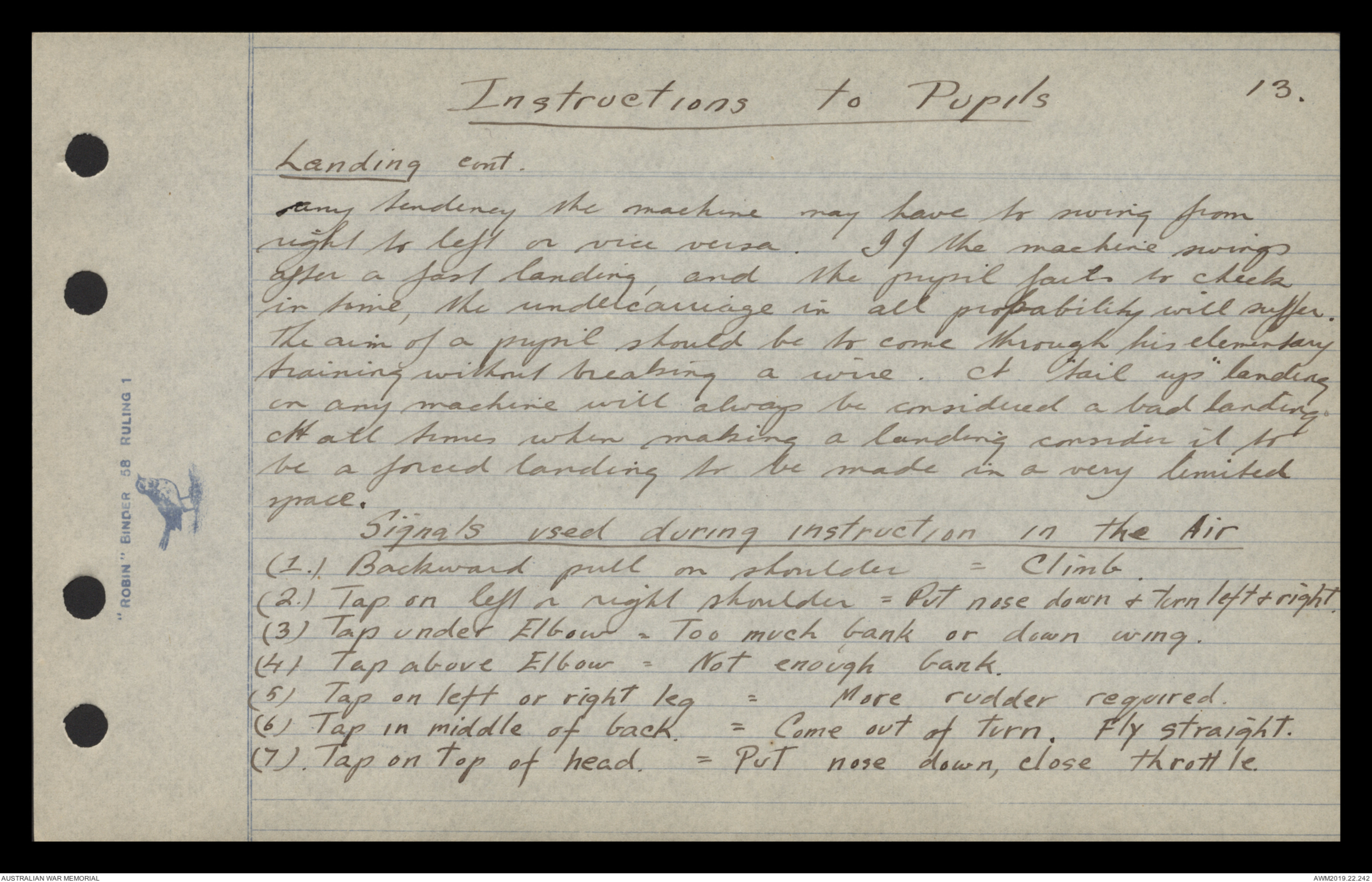
Landing cont.
any tendency the machine may have to swing from
right to left or vice versa. If the machine swings
after a fast landing, and the pupil fails to check
in time, the undercarriage in all probability will suffer.
The aim of a pupil should be to come through his elementary
training without breaking a wire. A "tail up" landing
in any machine will always be considered a bad landing.
At all times when making a landing consider it to
be a forced landing to be made in a very limited
space.
Signals used during instruction in the Air
(1.) Backward pull on shoulder = Climb.
(2.) Tap on left or right shoulder = Put nose down & turn left & right.
(3) Tap under Elbow = Too much bank or down wing.
(4) Tap above Elbow = Not enough bank.
(5) Tap on left or right leg = More rudder required.
(6) Tap in middle of back. = Come out of turn. Fly straight.
(7). Tap on top of head. = Put nose down, close throttle.
14
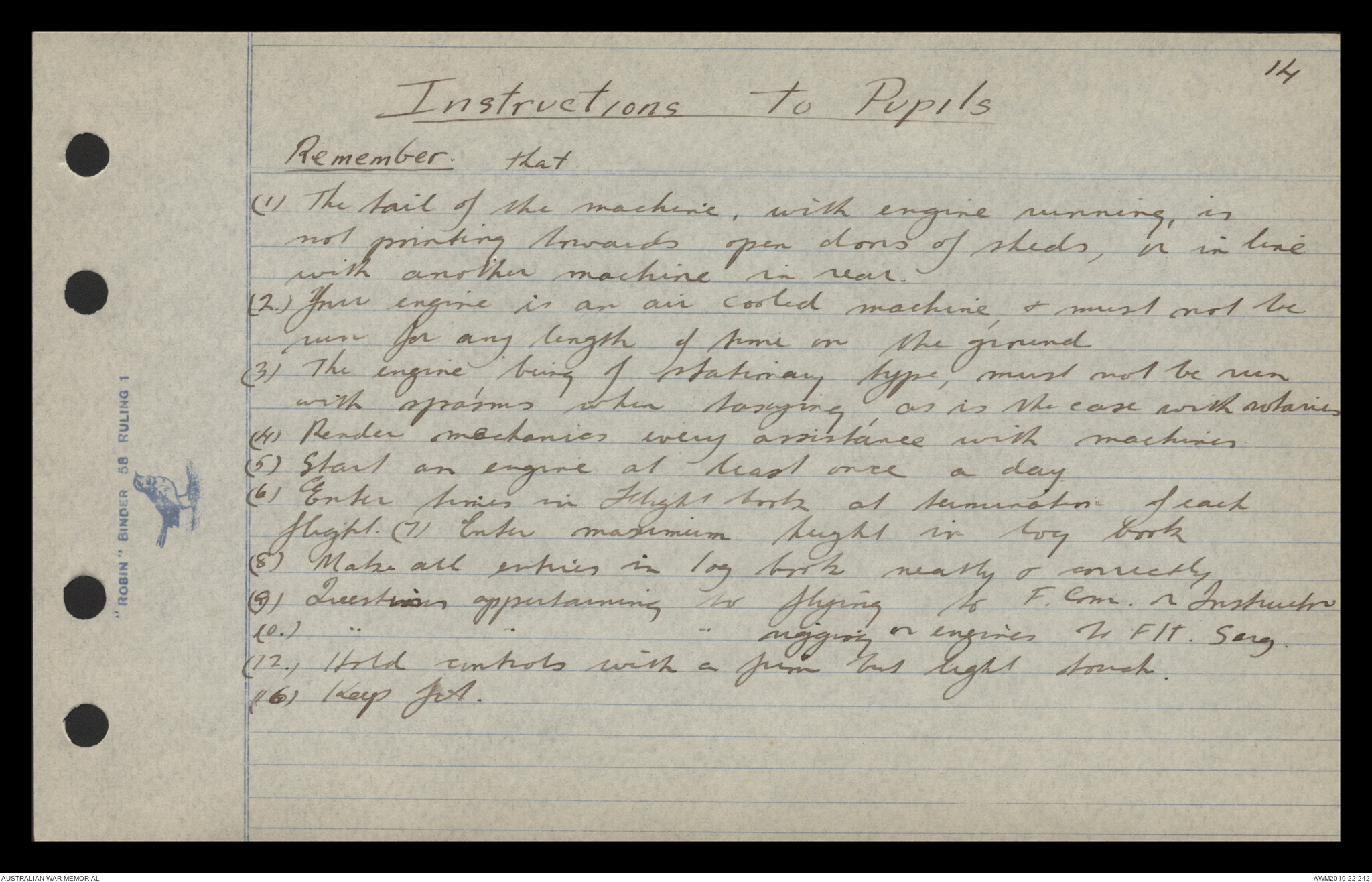
Instructions to Pupils
Remember. that
(1) The tail of the machine, with engine running, is
not pointing towards open doors of sheds, is in line
with another machine in rear.
(2.) Your engine is an air cooled machine, & must not be
run for any length of time on the ground
(3) The engine, being of stationary type, must not be run
with spasms when taxying, as is the case with rotaries
(4) Render mechanics every assistance with machines
(5) Start an engine at least once a day.
(6) Enter times in Flight book at termination of each
flight. (7) Enter maximum height in log book
(8) Make all entries in log book neatly & correctly
(9) Questions appertaining to flying to F.Com. or Instructor
(10) " " " rigging or engines to Flt. Sarg.
(12.) Hold controls with a firm but light touch.
(16) Keep fit.
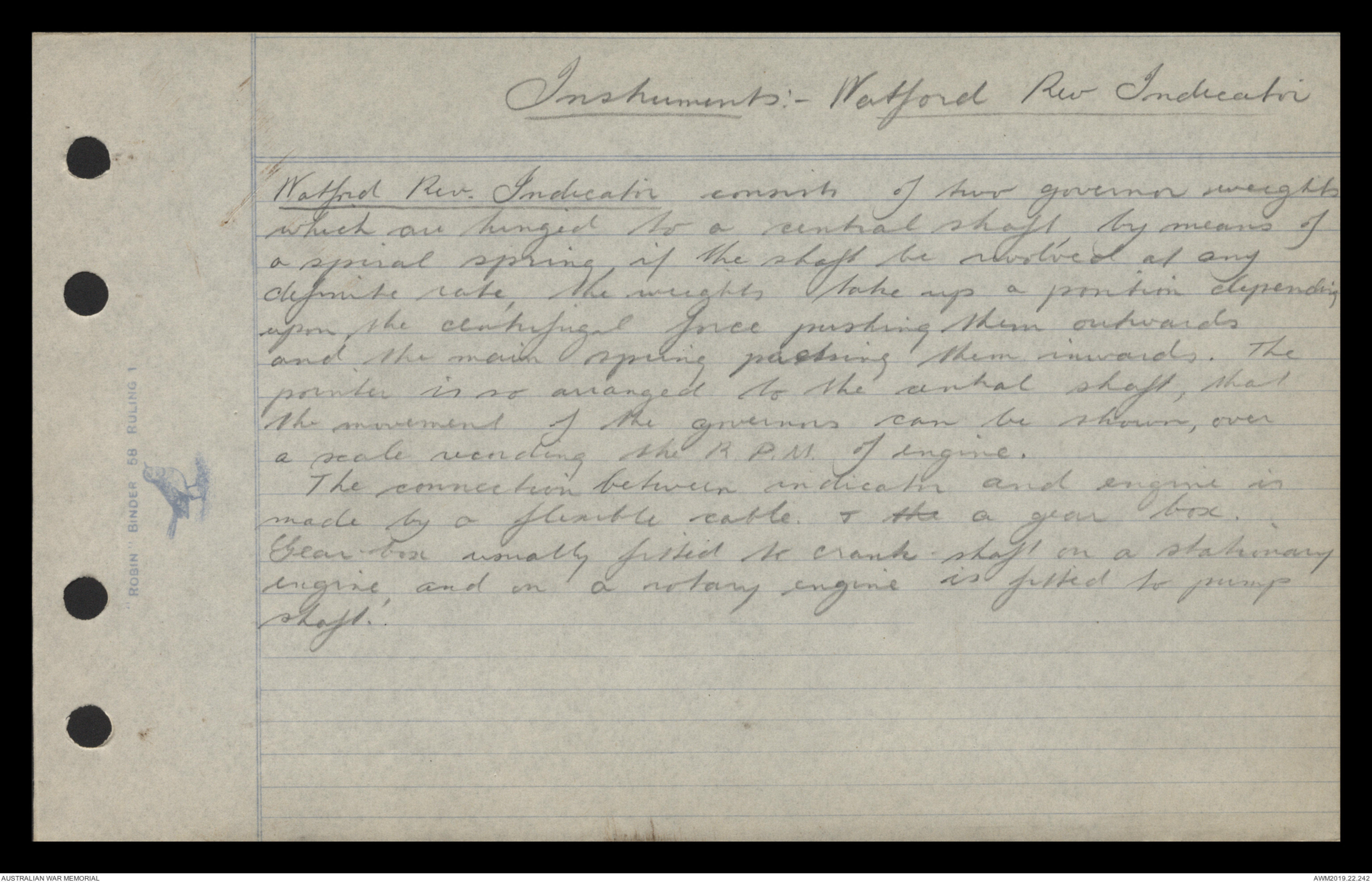
Instruments:- Watford Rev Indicator
Watford Rev. Indicator consists of two governor weights
which are hinged to a central shaft by means of
a spiral spring, if the shaft be revolved at any
definite rate, the weights take up a position depending
upon the centrifugal force pushing them outwards
and the main spring pushing them inwards. The
pointer is so arranged to the central shaft, that
the movement of the governors can be shown, over
a scale recording the R.P.M. of engine.
The connection between indicator and engine is
made by a flexible cable. & the a gear box.
Gear-box usually fitted to crank-shaft on a stationary
engine, and on a rotary engine is fitted to pump
shaft.
Instruments :- Watford Rev. Indicator
Diagram - see original document
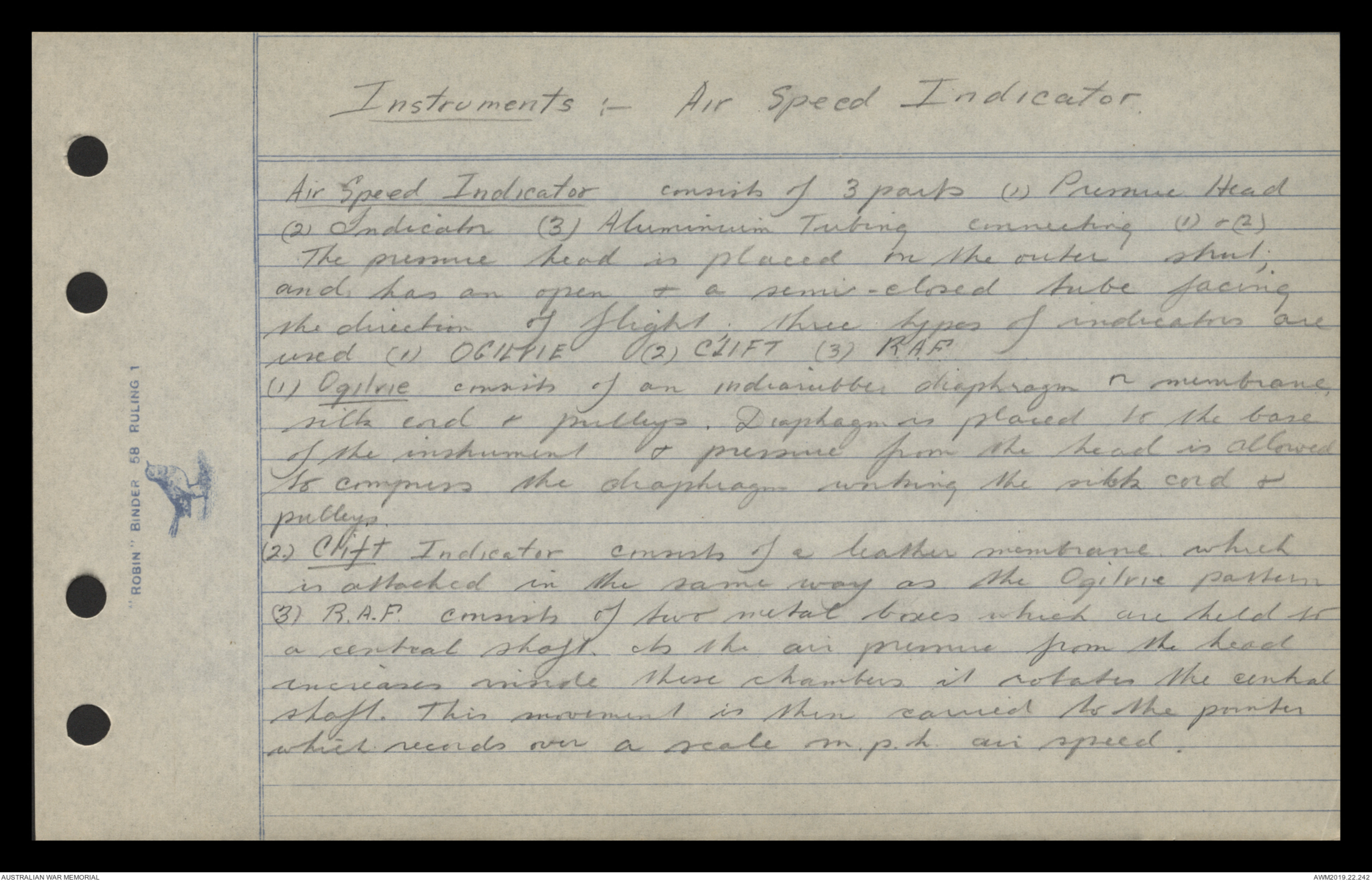
Instruments :- Air Speed Indicator.
Air Speed Indicator consists of 3 parts (1) Pressure Head
(2) Indicator (3) Aluminium Tubing connecting (1) & (2)
The pressure head is placed on the outer strut;
and has an open & a semi-closed tube facing
the direction of flight. three types of indicators are
used (1) OGILVIE (2) CLIFT (3) R.A.F.
(1) Ogilvie consists of an indiarubber diaphragm or membrane,
silk cord & pulleys. Diaphragm is placed so the base
of the instrument & pressure from the head is allowed
to compress the diaphragm working the silk cord &
pulleys.
(2.) Clift Indicator consists of a leather membrane which
is attached in the same way as the Ogilvie pattern
(3) R.A.F. consists of two metal boxes which are held to
a central shaft. As the air pressure from the head
increases inside these chambers it rotates the central
shaft. This movement is then carried to the pointer
which records over a scale m.p.h. air speed.
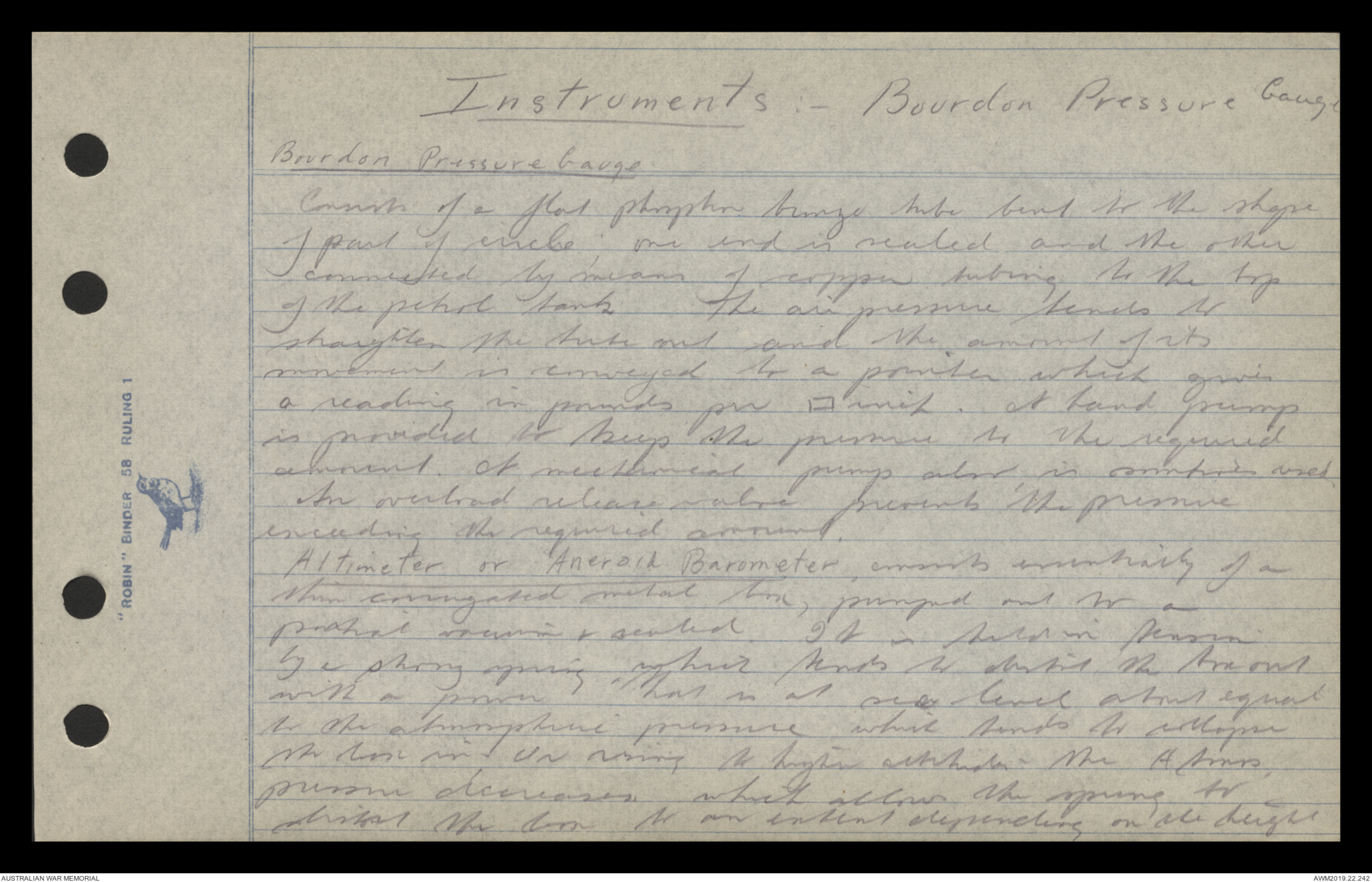
Instruments :- Bourdon Pressure Gauge
Bourdon Pressure Gauge.
Consists of a flat phosphor bronze tube bent to the shape
of part of circle; one end is sealed and the other
connected by means of copper tubing to the top
of the petrol tank The air pressure tends to
straighten the tube out and the amount of its
movement is conveyed to a pointer which gives
a reading in pounds per ▭ inch. A hand pump
is provided to keep the pressure to the required
amount. A mechanical pump also is sometimes used.
An overload release valve prevents the pressure
exceeding the required amount.
Altimeter or Aneroid Barometer, consists essentially of a
thin corrugated metal box, pumped out to a
partial vacuum & sealed. It is held in tension
by a strong spring, which tends to distort the box out
with a power that is at sea level about equal
to the atmospheric pressure which tends to collapse
the box in. On rising to higher altitude.- the Atmos,
pressure decreases. which allows the spring to
distort the box to an extent depending on the height
 Transcriber 6897
This transcription item is now locked to you for editing. To release the lock either Save your changes or Cancel.
This lock will be automatically released after 60 minutes of inactivity.