Service notebook of Harold Gordon Cornell - 1917 - Part 8
Engines :- 110 H.P. Clerget.
through the small end of shaft lubricating the gear box
Timing Ignition Place No I Cylinder at 22° before T.D.C
when it is on the compression stroke. To get the approx
position from a Y with Nos I & 9 Cyls at the top, No 5 vertical
at the bottom & secure the engine. Unmesh the
magneto & set it by turning the armature in a right
handed direction until the platinum points on the
contact breaker are about to break. Then carefully
mesh the magneto with the spur wheel by placing it
into position care being taken not to shift the armature
during the operation.
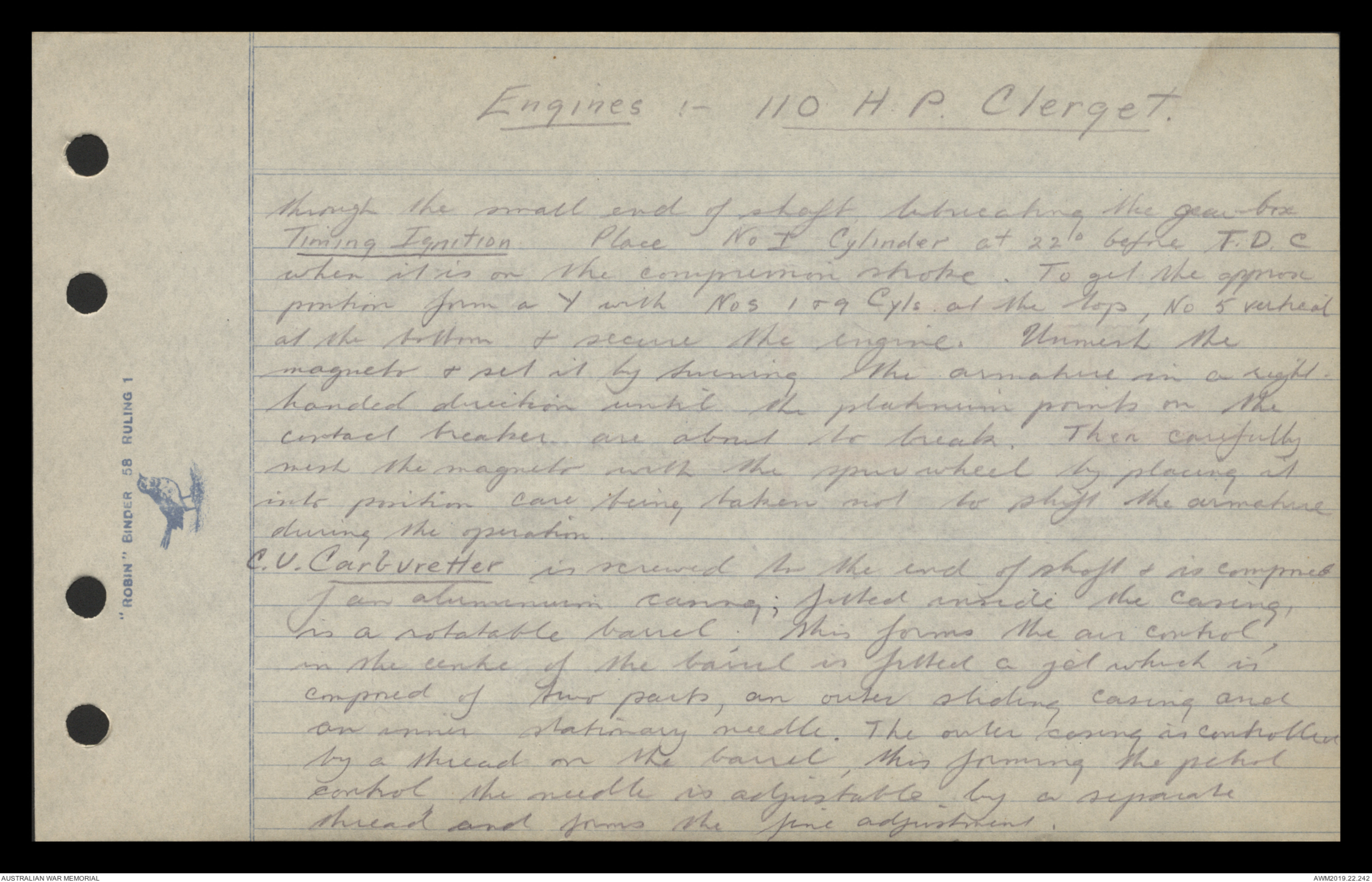
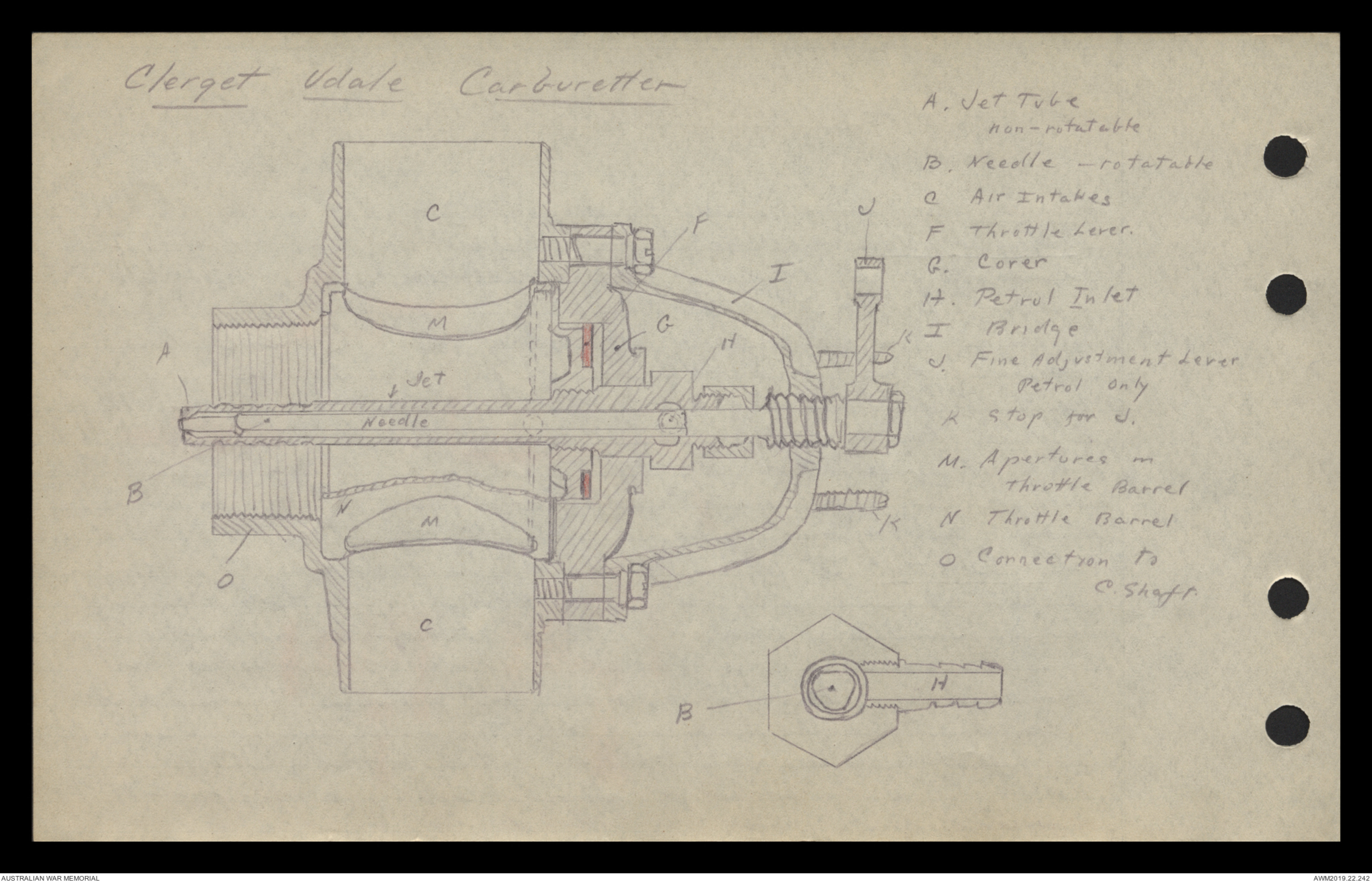
C.V. Carburetter is screwed to the end of shaft & is composed
of an aluminium casing; fitted inside the casing,
is a rotatable barrel; this forms the air control,
in the centre of the barrel is fitted a jet which is
composed of two parts, an outer sliding casing and
an inner stationary needle. The outer casing is controlled
by a thread on the barrel, this forming the petrol
control, the needle is adjustable by a separate
thread and forms the fine adjustment.
Clerget Udale Carburetter
Hand drawn diagram - see original document
110 H.P. Clerget
Clerget Oil Pump is bolted at the rear of the central
support, a pinion wheel protruding through a hole
and meshing with the spur wheel. The top portion
is composed of an aluminium casing, which contains
the gearing. The pump is of the piston and plunger type,
piston and plunger being dispersed by means of cams, &
returning to the up position by means of a strong spiral spring.
The bottom portion is of phosphor bronze & contains four
barrels two being for the piston & plunger & two to
contain the springs & guides. Oil is delivered by gravity
at the bottom of the pump and an inlet port is cut into
the piston barrel. & the piston & plunger barrels are
connected at the bottom by a channel.
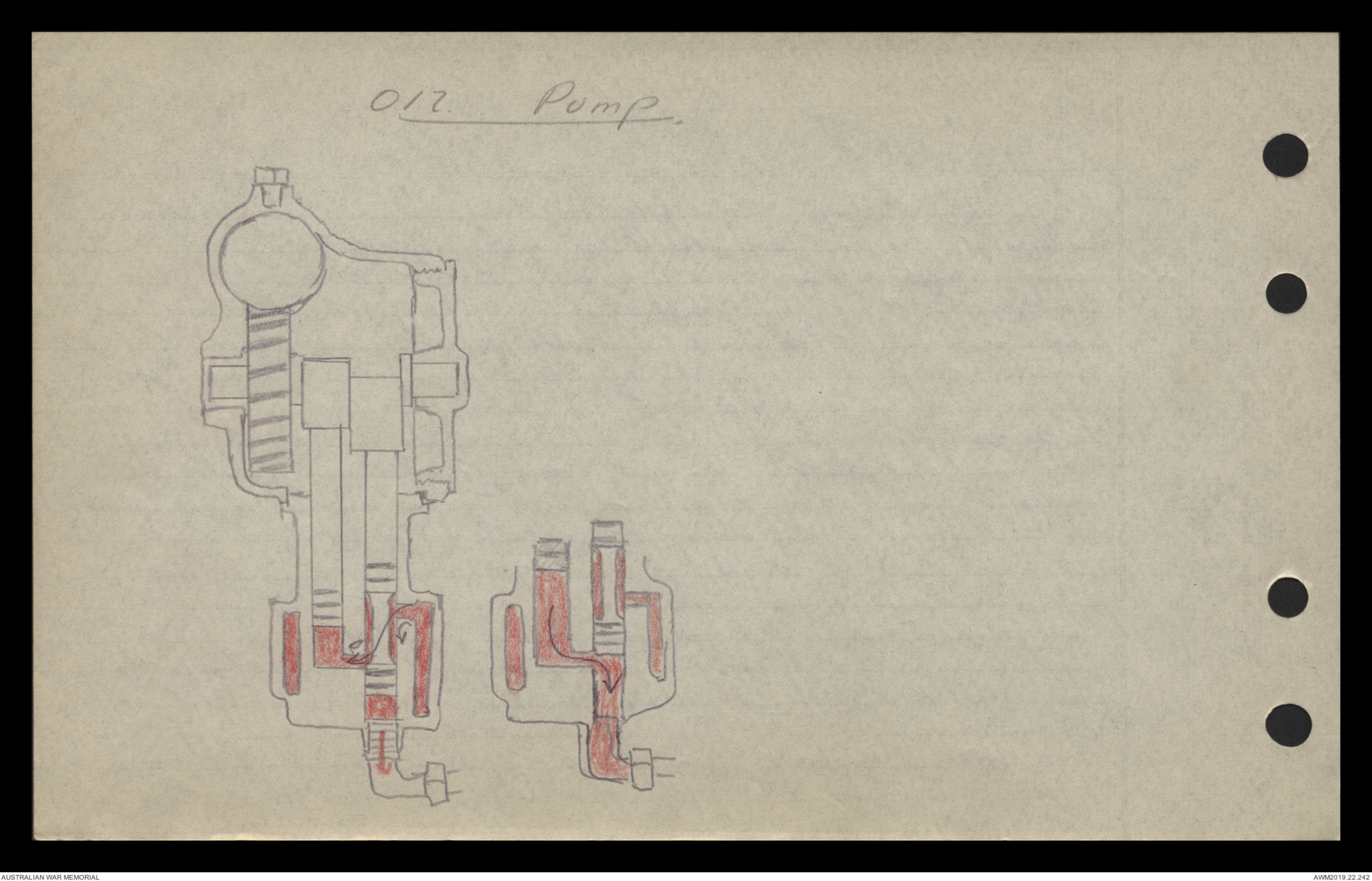
1st. Stroke Piston is depressed closing outlet to engine
which is at the bottom of its barrel & uncovering the
inlet port. 2nd Stroke Plunger is forced up sucking oil in
through inlet port along a channel into its own barrel
3rd Stroke Piston is forced up closing the inlet port
& uncovering the outlet to engine. 4th Stroke Plunger is
depressed forcing oil out of its barrel, along channel & out through outlet to engine
Oil. Pump.
Hand drawn diagram - see original document
110 H.P Clerget. — Air Pump.
Air-pump is driven off the spur wheel & is of the
piston & cylinder type. An aluminium cylinder casing contains
the gearing, which is similar to the oil pump,
a cast rim piston being driven in a steel cylinder.
Inlet ports are cut in the cylinder walls which are
uncovered by the piston, and by these, air enters
the cylinder;
when the piston on the return stroke covers the holes
the air remaining in the cylinder is forced out
through a delivery into the petrol tank. A non-return
valve is fitted to the outlet which is a ball & spring
valve, this preventing any back pressure from escaping
through the cylinder. A safety valve is fitted to
ensure an even pressure in the tank, about 4 lbs to ☐ inch
This is also worked by a ball & spring valve
1
Compass
Elementary Magnetism
Magnetism is an attractive & repulsive force, not a propulsive force
(e.g. the lines of a railway direct the engine to its destination
but do not propel it.). Almost entirely superficial,
little penetration of a magnetised substance; does
not increase wt, or volume, slightly elongates.
Definition: Object, when fuel suspended from C. of G., which points
to Magnetic Pole
All magnets 2 Poles, North Seeking & S.Seeking Ends
the World a magnet. Its Poles exert equal & opposite forces,
These forces direct. a M. Compass Needle to the M. Pole.
By convention, ^Magnetism of N.M. Pole is called Blue Magnetism, of S.M. Pole.
Red Magnetism. N.S. end of Magnet coloured Red, S.S. End blue
Like poles repel, unlike poles attract.
Lodestone or natural magnet. Artificial Magnets.
Substances may be rendered magnetic by:
(1) Percussion (2) electricity (3) Stroking with magnet (4) Electromagnetic.
Soft. Iron more susceptible to Magnetism than hard iron
not retentive; only Transient Magnetism
Test Magnetism by repulsion from another magnet.
The position of the N. Magnetic Pole does not correspond
2
Compass - Elementary Magnetism
with that of the True or Geographical North Pole. It is
supposed to move elliptically round the true North,
& now is moving slowly Eastward. It is situated over
1000 miles S of the true pole, to the W. of Geographical
meridian. The two meridians drawn from Greenwich
contain an angle of 15°. This is what is known as
the magnetic variation.
The free exercise by magnetism has two components
Horizontal & a Vertical; the latter is compensated
for mechanically in the manufacture of compasses.
3
Compasses
All compasses work on exactly the same principle,
no matter how they may vary in construction. With
the exception of the magnetised needles all parts
of a compass are made of non-magnetic material,
such as brass, aluminium, bronze, & white metal.
The parts of a compass are.:-
The Box or in the case of the Admiralty Pattern,
the Containing Ring
The Corrector Box or Magnet Holder in which are
placed the correcting magnets, which are used to
adjust the compass
The Anti-Vibration Springs & Buffers - The springs are
of phosphor-bronze. The buffers are of felt or fibre.
These are necessary to deaden the vibration of the
engine. & to lessen the shock on landing. They
allow the bowl of the Compass a certain amount of free
play in all directions.
The bowl is fitted with distilled water & alcohol
to act as a damper on the movements of the compass
card and so render it less sensitive to disturbance
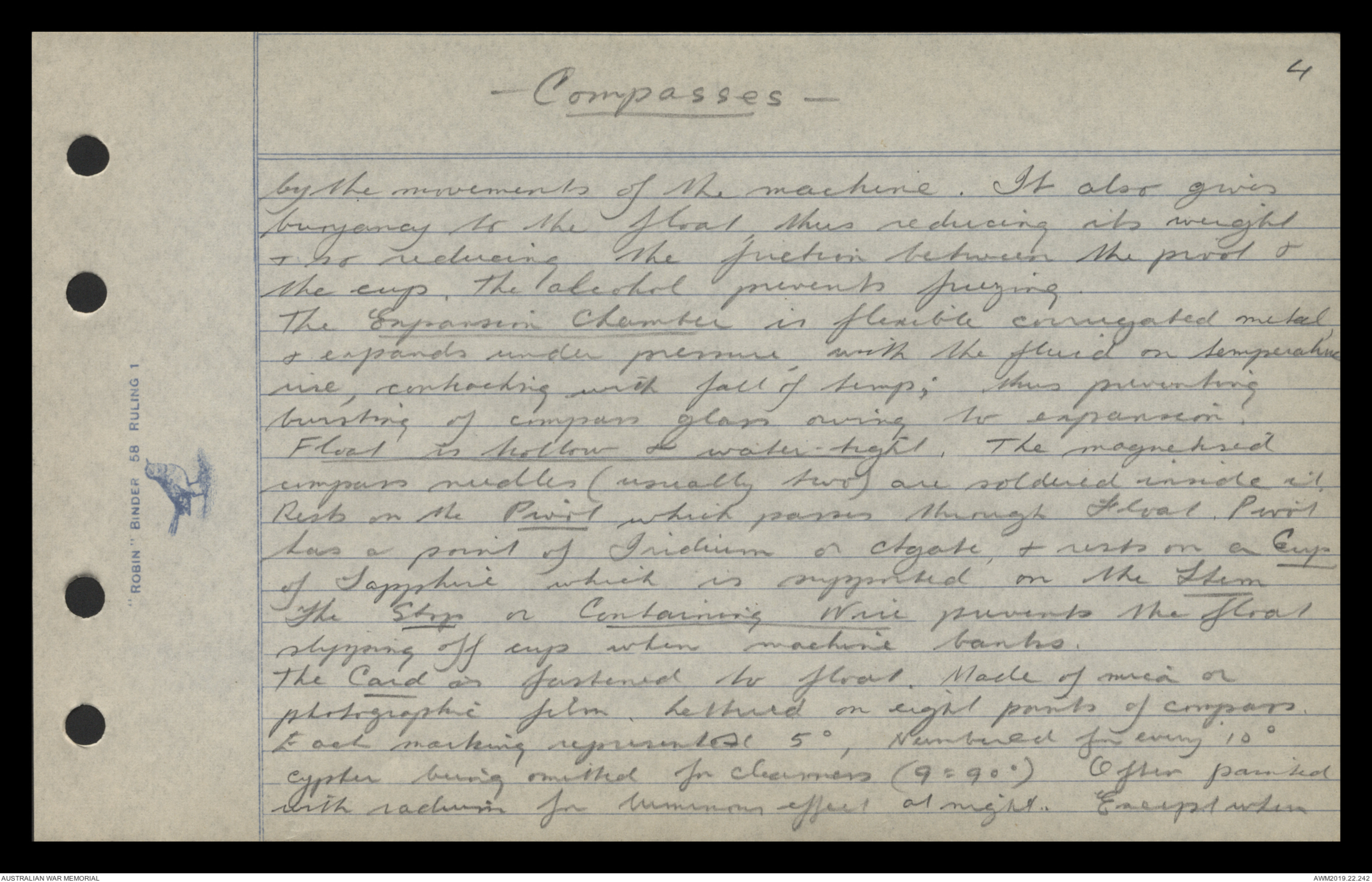
4
Compasses
by the movements of the machine. It also gives
buoyancy to the float, thus reducing its weight
& so reducing the friction between the pivot &
the cup. The alcohol prevents freezing.
The Expansion Chamber is flexible corrugated metal,
& expands under pressure, with the fluid on temperature
rise, contracting with fall of temp; thus preventing
bursting of compass glass owing to expansion.
Float is hollow & water-tight. The magnetised
compass needles (usually two) are soldered inside it.
Rests on the Pivot which passes through Float. Pivot
has a point of Iridium or Agate, & rests on a Cup
of Sapphire which is supported on the Stem
The Stop or Containing Wire prevents the float
slipping off cup when machine banks.
The Card is fastened to float. Made of mica or
photographic film. Lettered on eight points of compass.
Each marking represents 5°, Numbered for every 10°
cypher being omitted for clearness (9 = 90°) Often painted
with radium for luminous effect at night. Except when
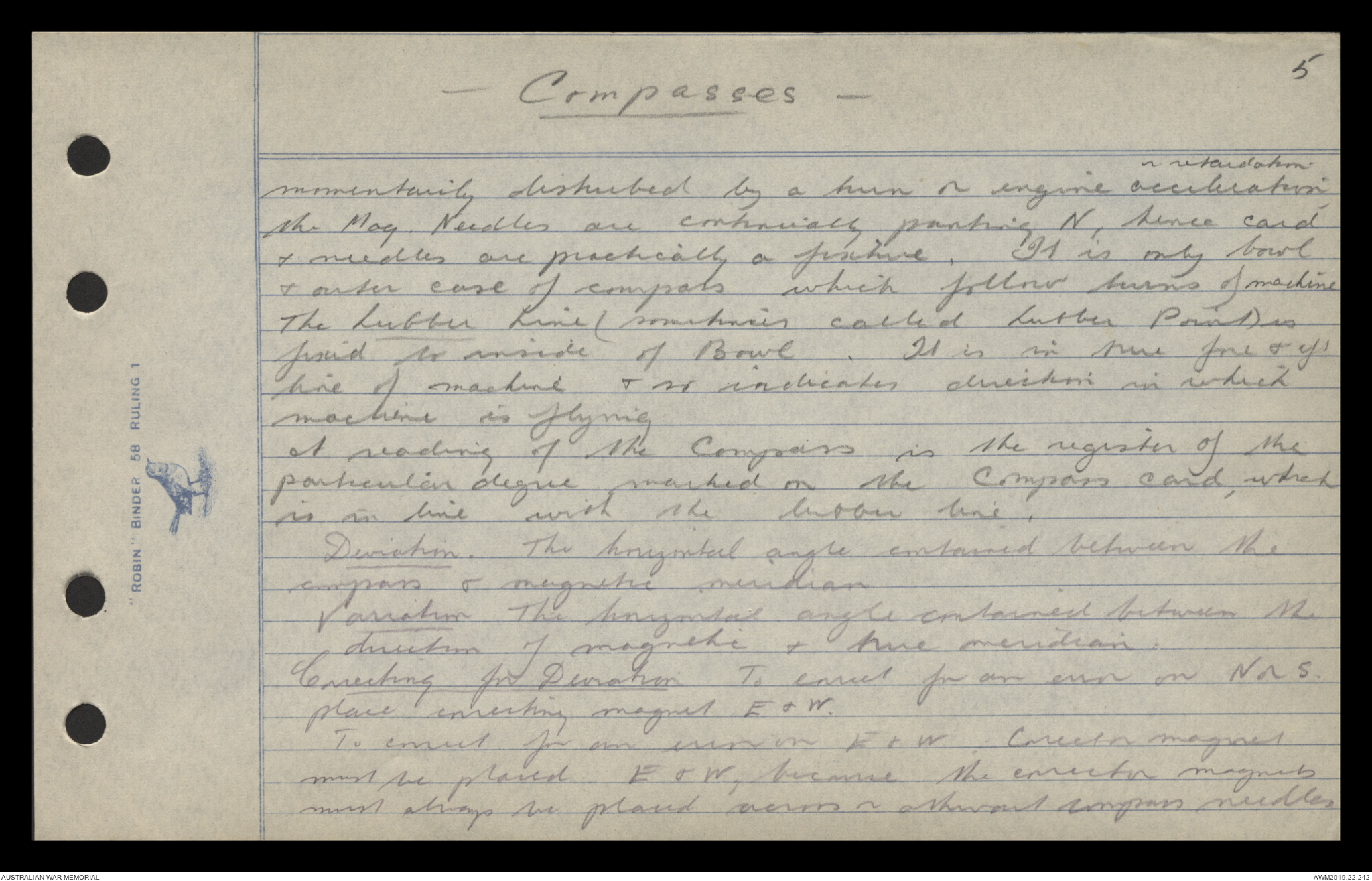
5
Compasses
momentarily disturbed by a turn or engine acceleration or retardation,
the Mag. Needles are continually pointing N, hence card
& needles are practically a fixture. It is only bowl
& outer case of compass which follow turns of machine
The Lubber Line (sometimes called Lubber Point) is
fixed to inside of Bowl. It is in true fore & aft
line of machine & so indicates direction in which
machine is flying
A reading of the Compass is the register of the
particular degree marked on the Compass card, which
is in line with the lubber line.
Deviation. The horizontal angle contained between the
compass & magnetic meridian.
Variation The horizontal angle contained between the
direction of magnetic & true meridian.
Correcting for Deviation To correct for an error on N or S.
place correcting magnet E & W.
To correct for an error on E & W; Corrector magnet
must be placed E & W, because the corrector magnets
must always be placed across or thwart compass needles
 Transcriber 6897
This transcription item is now locked to you for editing. To release the lock either Save your changes or Cancel.
This lock will be automatically released after 60 minutes of inactivity.