Service notebook of Harold Gordon Cornell - 1917 - Part 7
Engines:- 110 H.p. Clerget
and to evenly distribute lubrication on the cylinder walls
which comes through holes drilled immediately below
the last groove on the piston skirt.
Gudgeon Pins are of case-hardened steel & are parallel
being made solid; they are secured by a set screw
passing through a hole in the lug, & screwing into the
gudgeon pin, set screw being secured by a split steel
ring passing through a hole in the head, & clamping
around the lug.
Crank Case is a drop steel forging, and is made in
two halves, cylinders being clamped between, & the
halves secured by a bolt passing between each cylinder
into which fits the collar turned on the cylinder
this preventing the cylinders being blown off, cylinders
being prevented from turning by a small key, between
cylinder & crank case. Crank case is supported by
being bolted at the back to the thrust box & at the
front to the gear box, which in turn are supported on the
shaft by ball bearings.
Engines:- 110 H.P. Clerget
Cylinders are of Ch Ni Steel, turned from a forging; thickness
of cylinder walls 3mm. A collar is turned on the skirt
which fits into a recess, turned in the crank-case, this
preventing the cylinder from being blown off; they are
prevented from turning by a small key, fitting between
crank-case & cylinder. Fins are turned for cooling &
strengthening purposes & two holes are drilled in the
head to accommodate the valves, the seatings of these
being screwed into the cylinder. Two brackets are
also screwed in to carry the ricker arms which operate
the valves. Provision is made for 2 sparking plugs, one
at the leading edge & one at the rear (Later engines both plugs
in front). Cylinders must be kept bright & clean to
enable internal defects to be discovered from the
outside.
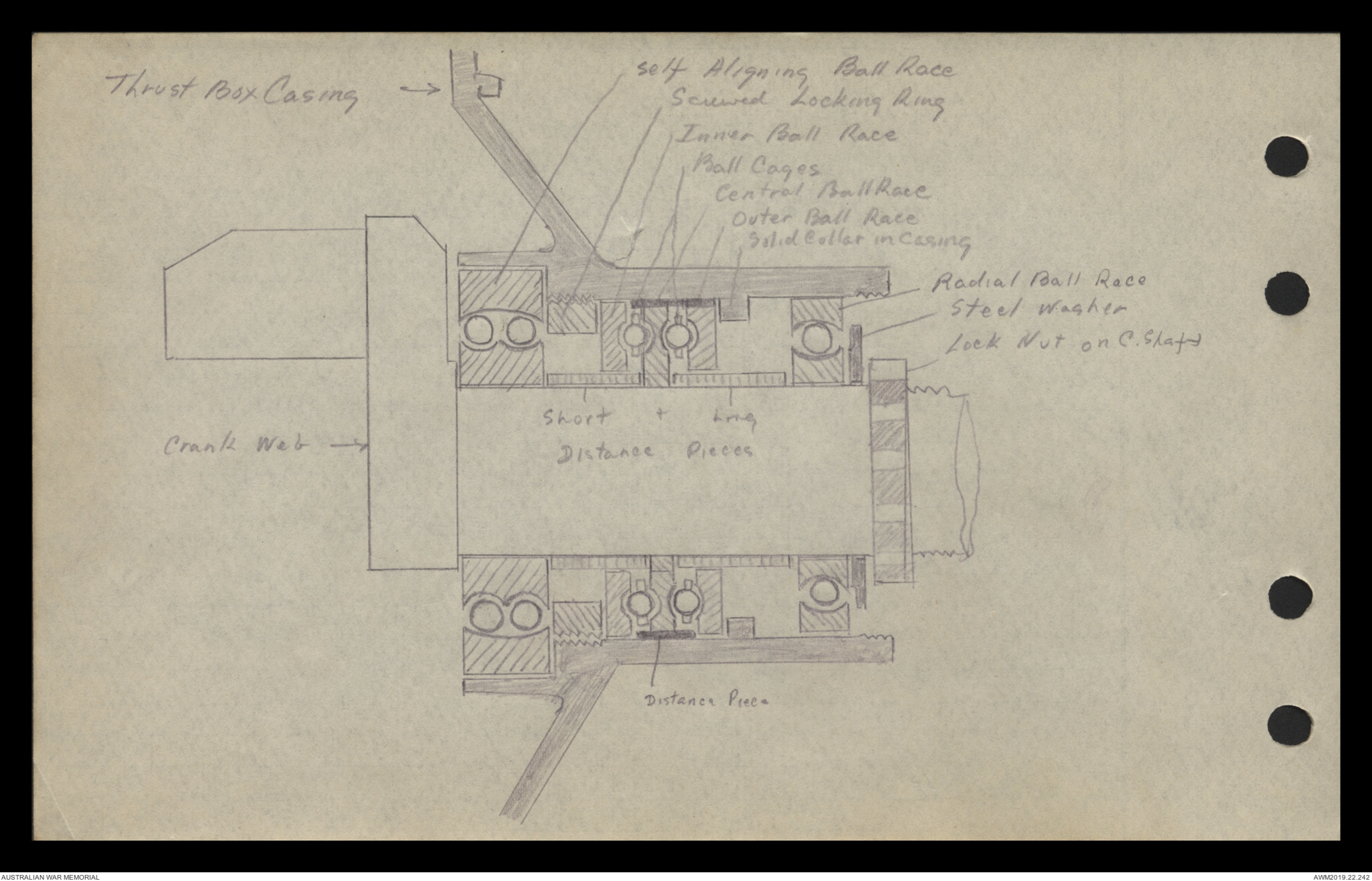
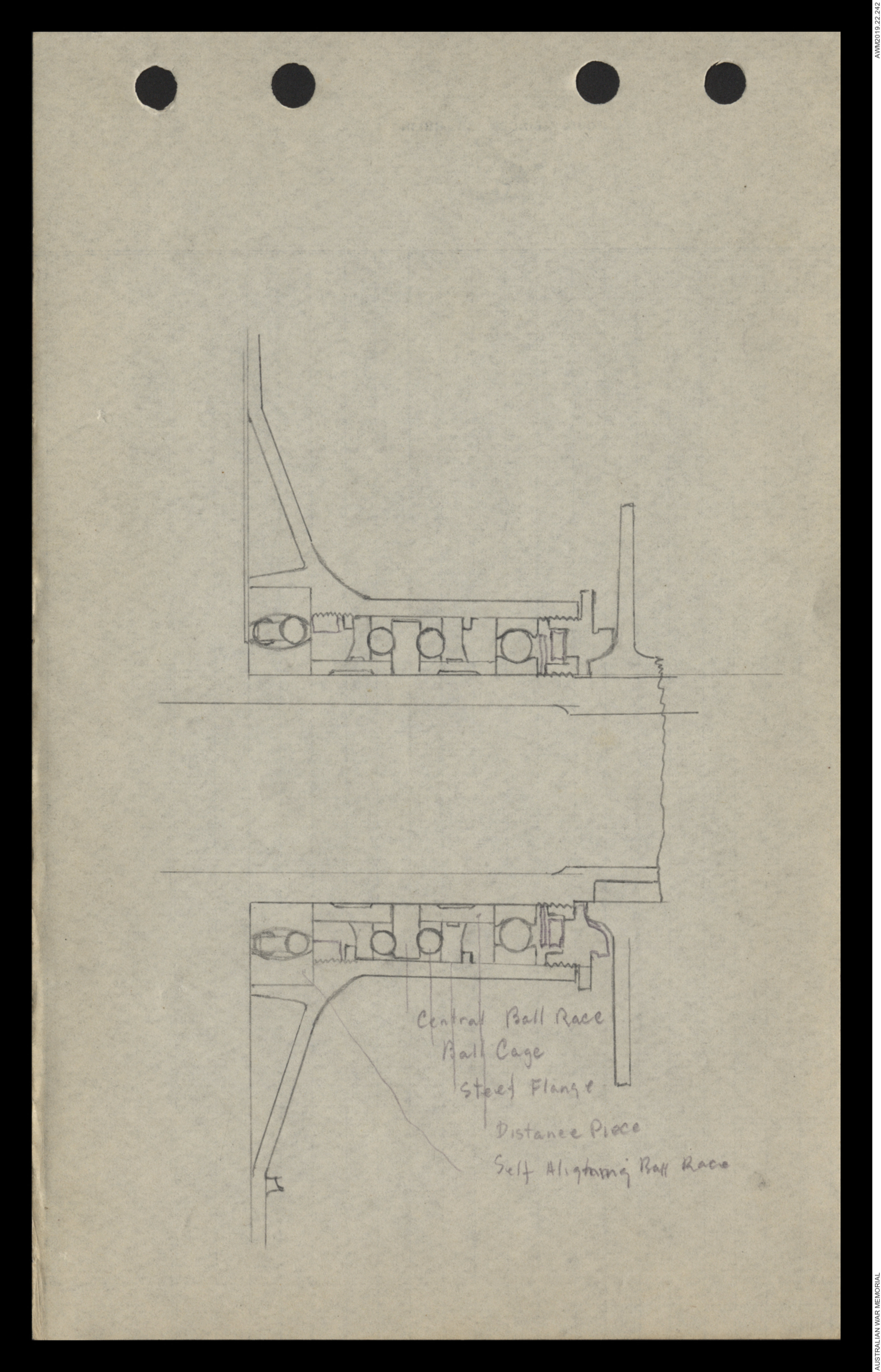
Thrust Box is situated on the rear of engine rotates on the
long end of shaft & is supported by two ball bearings
one being radiant and one self-aligning. It carries the
spare wheel, which is used to drive the auxiliaries, viz.
oil pumps, air pumps & magnets, & also the distributor ring
Hand drawn diagram - see original document
Engines:- 110 H.P. Clerget
which is used to collect current from a stationary carbon
brush & convey it by means of a wire to the plug
Between the two ball bearings is fitted a double-active,
thrust race, which is designed to take thrust, both
in tractor & pusher directions.
Tractor Thrust is first taken on a solid collar turned in
the thrust box, through the outer ball race, to the outer
ball cage, then to the central ball race, on to the
distance price, through the s.a. ball bearing to the crank
web.
Pusher Thrust is just taken on a screwed collar, screwed into the
thrust box through the inner ball race to the inner ball cage,
then to the central ball race, distant price radial bear bearing
& is finally taken by a locking nut screwed in the shaft.
Hand drawn diagram - see original document
110 H.P. Clerget
Valve Cleaning & Timing
Valves are mechanically operated by a system of
gears maintained in a gear box which rotates on
small end of shaft. In the centre of the gear-box
is placed a ball bearing which supports it on the shaft.
18 holes ate drilled around the gear box these being
bushed with phosphor bronze, for the guides for the
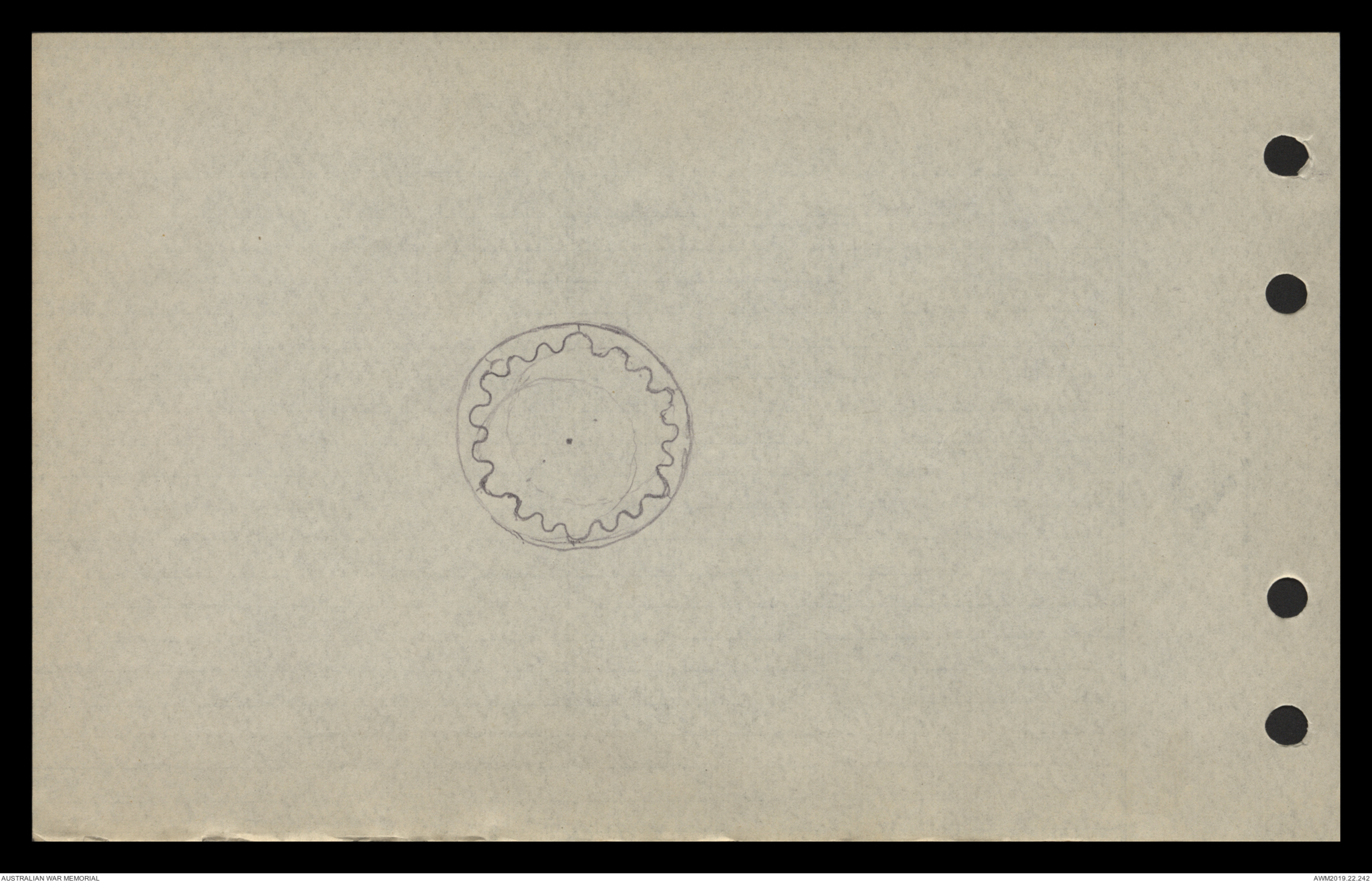
tappets. Keyed into the gear box are two internally
toothed rings which are used to drive the inlet &
exhaust cam wheels. They have 18 teeth & run
concentric with the crank shaft. On the eccentric
shaft are placed two externally toothed wheels which
have 16 teeth & run eccentric to the shaft : only
meshing with the gear ring at one point. On each
fourth tooth of the gear which is an extension or cam
& this wheel gains two teeth for every revolution of the
engine. On one revolution an extension comes on
alignment with the tappet & pushes open the valve
but on the next revolution the wheel having gained two
teeth the tappet drops into the recess behind & the valve
Hand drawn diagram - see original document
110 H.P. Clerget
is not opened. On the 3rd revolution, two more teeth
having then gained the next extension comes in
alignment & the valve is opened. By this means
the valve is opened once every two revs.
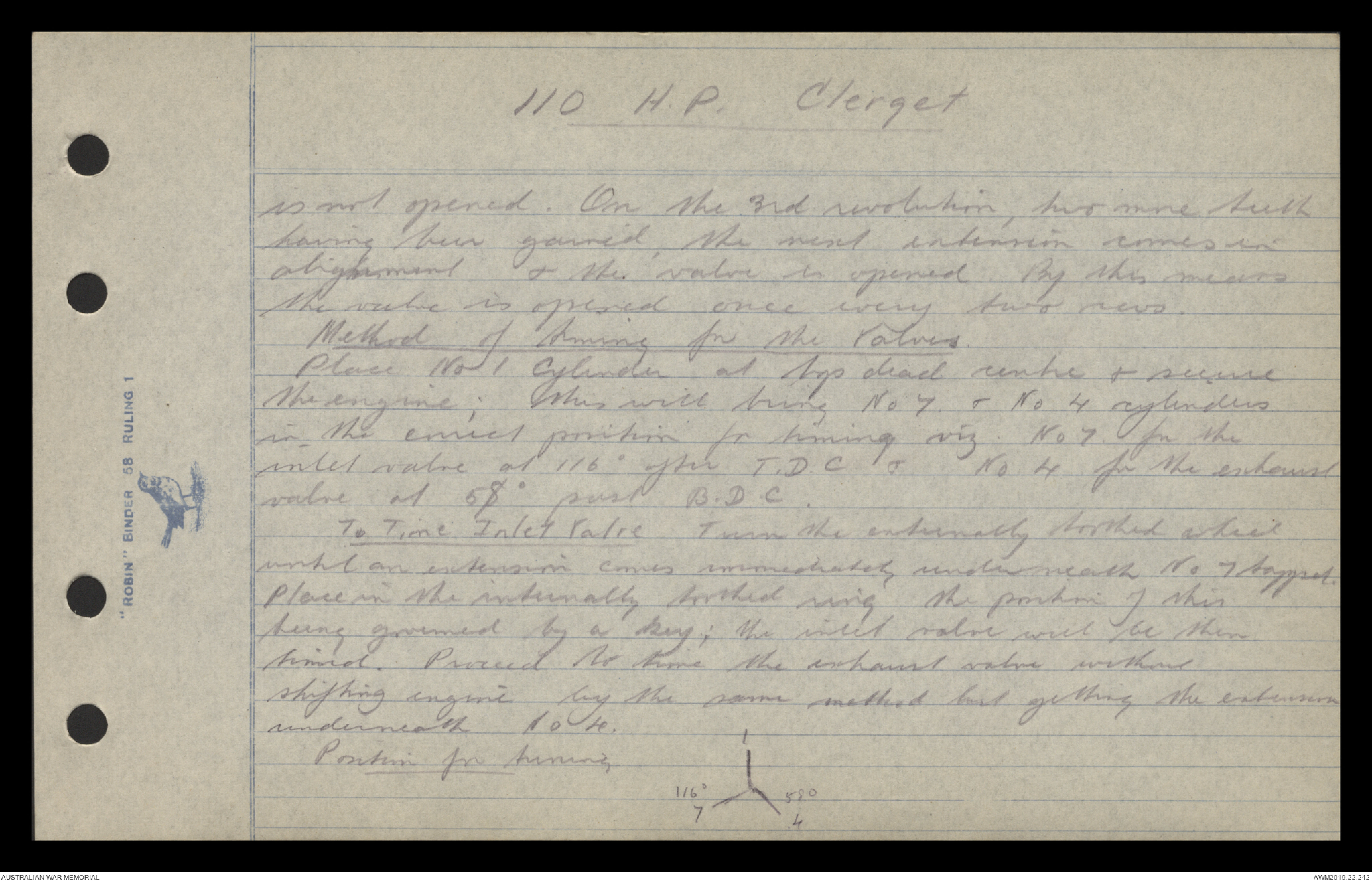
Method of timing for the Valves
Place No 1 Cylinder at top dead centre & secure
the engine; this will bring No. 7 & No 4 cylinders
in the correct position for timing viz No 7 for the
inlet valve ay 1100 after T.D.C. & No. 4 for the exhaust
valve at 580 past B.D.C.
To Time Inlet Valve Turn the externally toothed which
until an extension comes immediately underneath no 7 tappet
Place in the internally toothed ring the position of this
being governed by a key; the inlet valve will be then
timed. Proceed to time the exhaust valve without
shifting engine by the same method but getting the extension
underneath No 4.
Position for timing
Hand drawn diagram - see original document
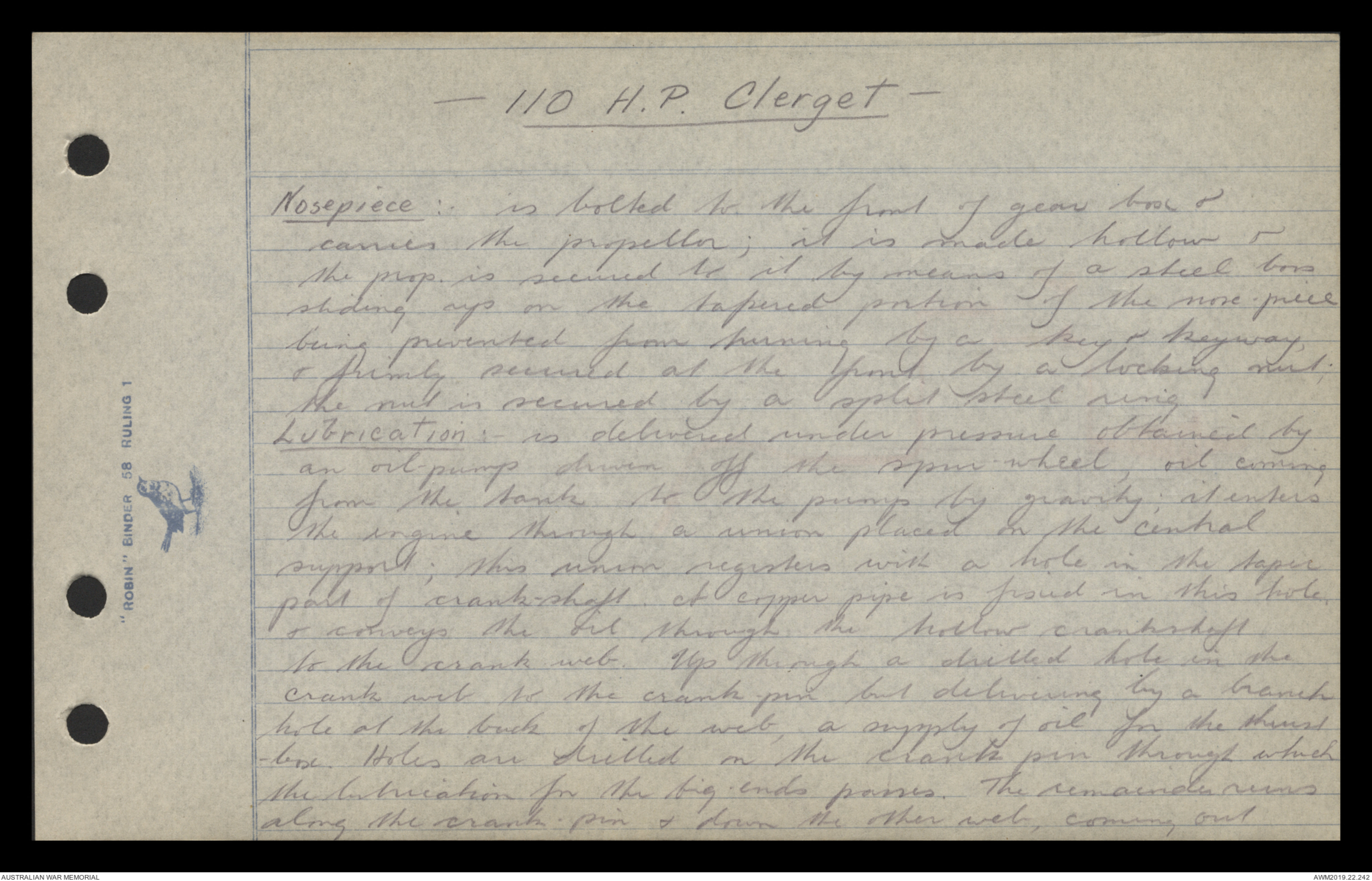
-110 H.P. Clerget -
Nosepiece:- is locked to the front of gear box &
carries the propellor; it is made hollow &
the prop is secured to it by means of a steel box
sliding up on the tapered portion of the nose-piece
being prevented from turning by a key & keyway,
& firmly secured at the front by a locking nut;
the nut is secured by a split steel ring.
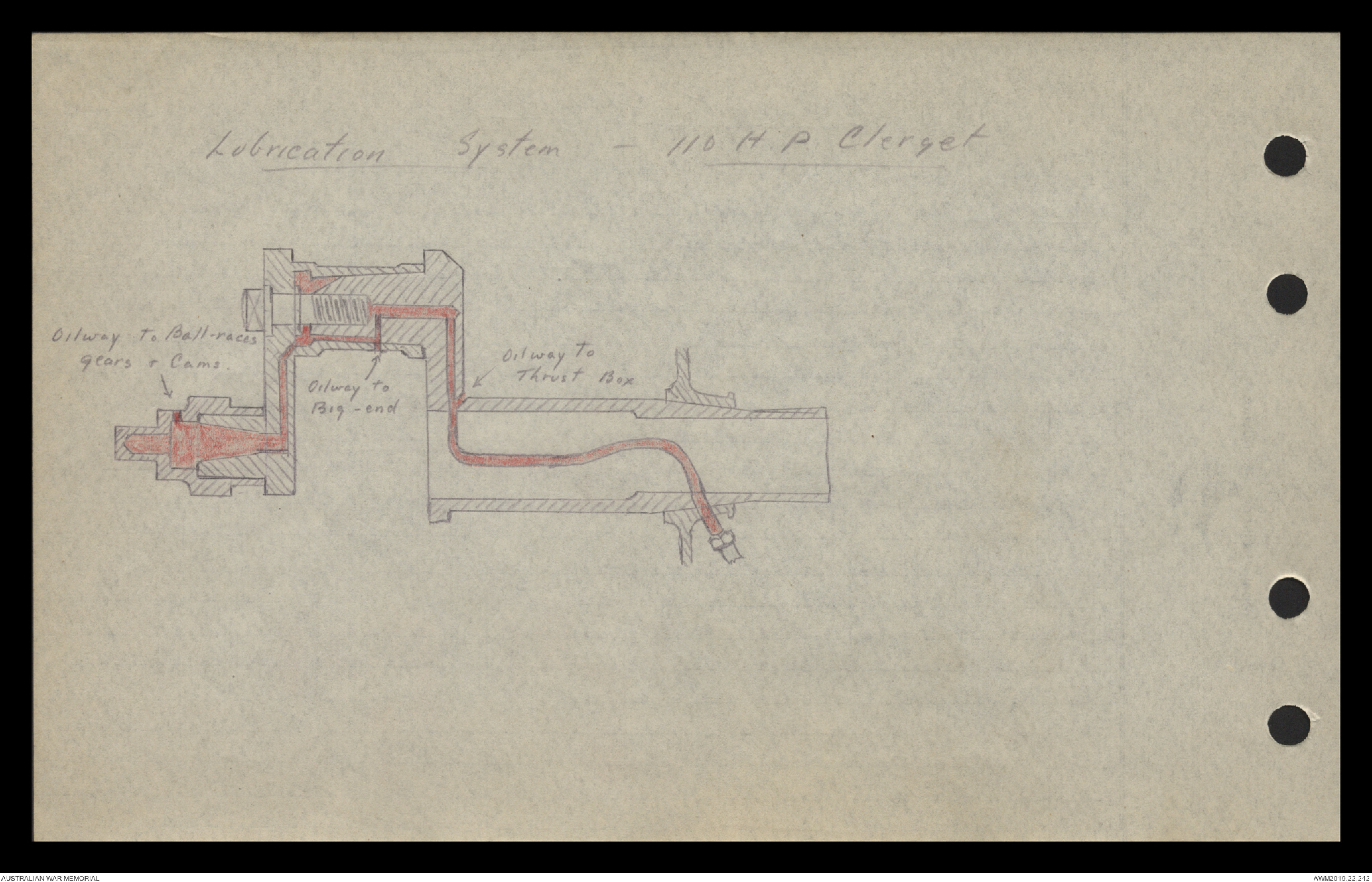
Lubrication: is delivered under pressure obtained by
an oil pump driven off the spare wheel, oil coming
from the tank to the pump by gravity; it enters
the engine through a union placed in the central
support; this union registers with a hole in the tapir
part of the crankshaft. A copper pipe is fixed in this hole
& conveys the oil through the hollow crankshaft
to the crank web. Up through a drilled hole in the
crank web to the crank pin but delivering by a branch
hole at the back of the web, a supply of oil for the thrust
box. Holes are drilled on the crank pin through which
the lubrication for the big-ends passes. The remainder runs
along the crank pin & down the other web, coming out
Hand drawn diagram - see original document
 Jen
Jen This transcription item is now locked to you for editing. To release the lock either Save your changes or Cancel.
This lock will be automatically released after 60 minutes of inactivity.