Service notebook of Harold Gordon Cornell - 1917 - Part 6
−Bombs −
Precautions (cont)
(3) Bomb to be screwed down by tail support to
steady it during flight
(4) Safety transit pins to be withdrawn or
replaced by suitable safety devices
−Bombs −
Points to be attended to before starting out on
a bombing raid
1. See to bombright
2. Bomb-racks working
3. Draw bombs into with full complement of essential parts
4. Fuzes in working condition
Points (1) Threads not cleaned with petrol
(2) Striker blunt
(3) Creep spring in order
5. Safety pins withdrawn prior to flight
Diagramatic Sketch of bomb or fuse
Diagram- see original document
−Bombs −
Safety devices & uses of pistol tail fuse (rough sketch)
(1) Safety Vane. }
(2) Safety Pin } Keys striker off detonator
(3) Creep Spring }
(4) Cord . Prevents wind vane rotating
(5) Safety Adjustment Pin (Clips over Vane in rack
Copper Fuse & Nose Fuse (certain questions)
Diagram- see original document
Action of fuse from release so
explosion
(1) Wind rotates propeller
(2) Prop rotates striker
(3) Striker " gearwheel
(4)A camwheel " Needle carrier
(5) This brings needle packet into line with
striker & detonator
On Impact (6) Prop & striker forced out
(7) Plunger cuts shear wire
(8) This forces striker needle into detonator
1.
Engines : - 110 H.P. Clerget.
General Data :-
9 Cyl. rotary Engine Petrol Consumption 10galls p.hr
Bore 120 mm. Oil " 1¾ " " "
Stroke 160 " " Revs p.m. on ground 1150
Weight 395 lbs " " in air 1200.
Lubrication used Castor Oil, Direction of Rotation Left Hand.
because necessary for Oil & Petrol tp
enter Cylinders together, C.O will not
mix with Petrol
The internal combustion engine is worked under what is
known as the Other Cycle or four-stroke principle which
makes it necessary to empty 3 strokes to prepare the
engine for one actual stroke of power. The names of the
strokes are (1) Induction (2) Compression (3) Power (4) Exhaust.
Cycle of Operations
Induction Stroke, Inlet valve is opened at 4° before
top dead centre & petrol mixture is drawn into the
cylinder until 56°past bottom d.c., the valve then closes
Compression lasts from 56° past, B.D.C. until T.D.C., but
ignition occurs at 22° before T.D.C.
2.
Engines : - 110 H.P. Clerget
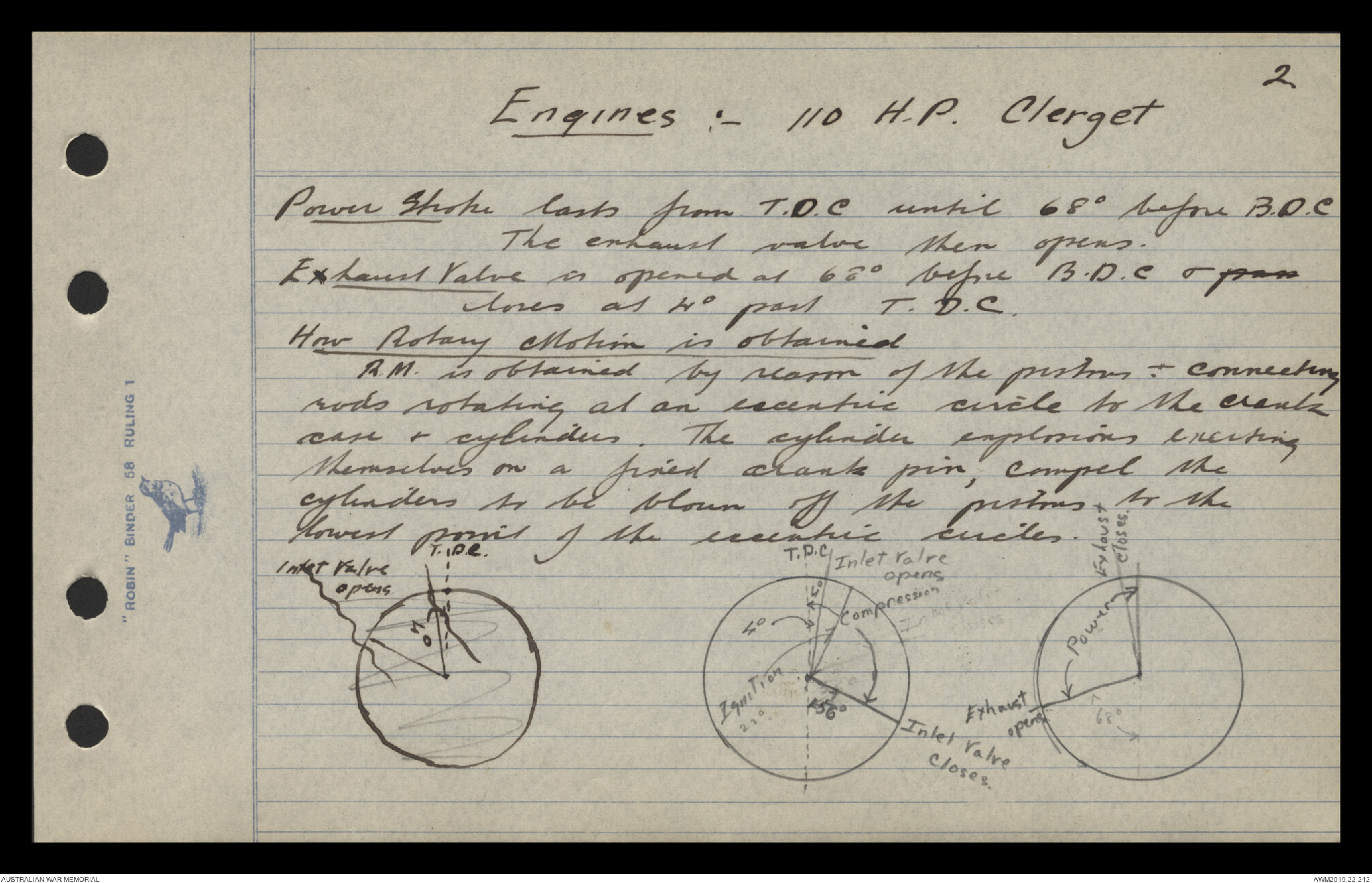
Power Stroke lasts from T.D.C. until 68° before B.D.C.
The exhaust valve then opens.
Exhaust Valve is opened at 68° before B.D.C. & open
closes at 4° past T.D.C.
How Rotary Motion is obtained
R.M. is obtained by reason of the pistons - connecting
rods rotating at an eccentric circle to the crank
case & cylinders. The cylinder explosions enciting
themselves on a fixed crank pin, compel the
cylinders to be blown off the pistons to the
lowest point of the eccentric circles
Diagram- see original document
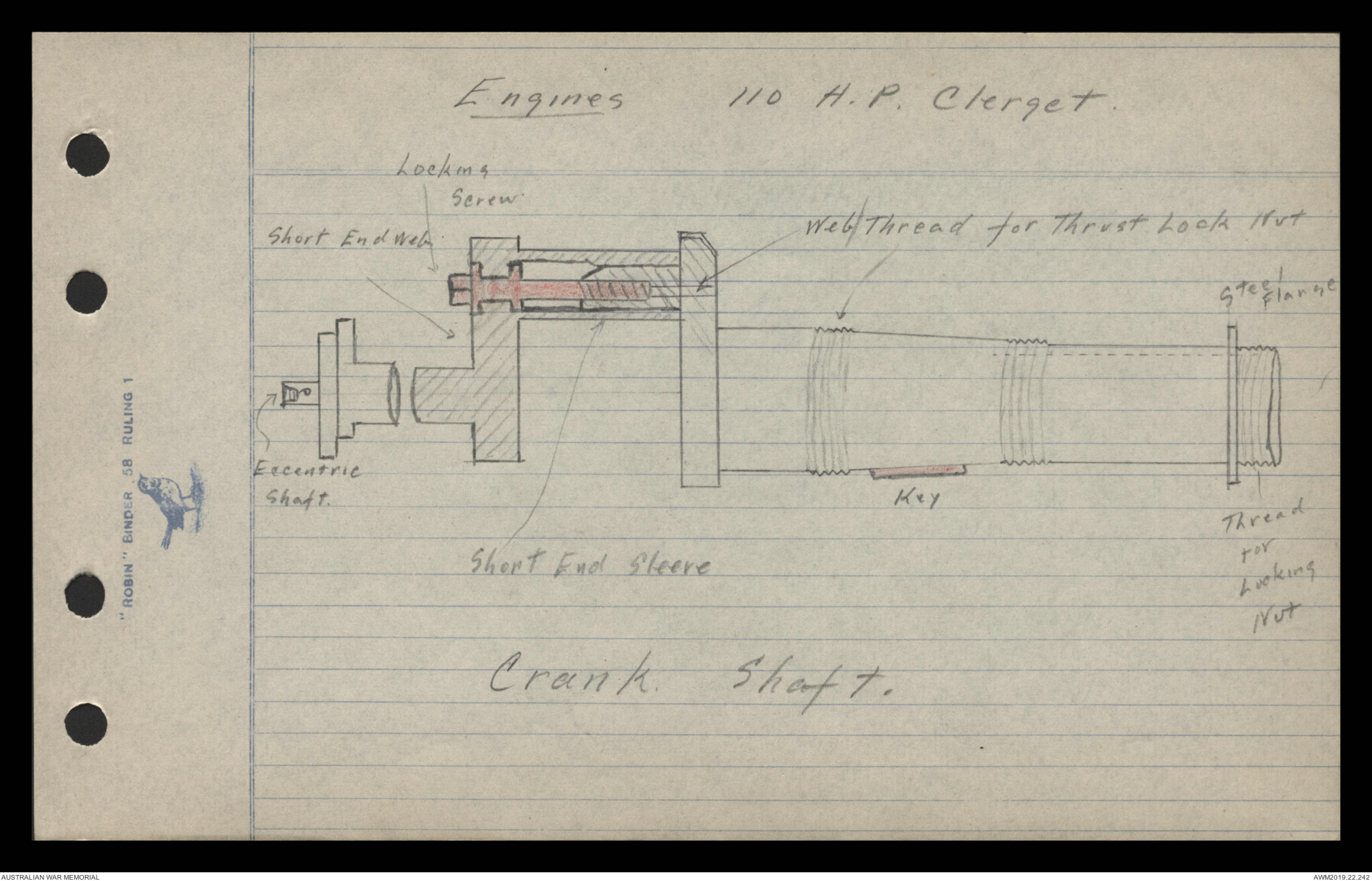
Engines : - 110 H.P. Clerget
Diagram- see original document
Crank Shaft.
3
Engines : - 110 H.P. Clerget.
Description & uses of the Crank-shaft.
The C.S. is of chrome nickel steel, and is built up
of three parts, viz long ens (hollow), small end &
eccentric shaft or maneton which fits on the end of the
small end.
The small end of the shaft fits over the crank-pin
by means of a sleeve which is kept in alignment by
a key & a keyway & secured at the front by a set bolt.
which has a double collar & screws into the crank pin,
by this means forming an extractor. Crank pin is
chamfered on top to enable matter connecting rod
to be taken off whilst the engine is still in the
machine
Uses (1) Forms the centre of rotation of the engine
(2) " means of attaching engine to the machine.
(3) " the fixed points upon which rotary motion
is obtained (break pin)
(4) Conveys oil to working parts & petrol to the
crankcase.
4.
Engines : - 110 H.P. Clerget.
Method of securing engine to machine
Engine is secured to machine by the long-end
of shaft, passing through two bearer plates which
are bolted to the machine, (Central support, rear support).
being secured at the back of the central supports
by a tracking sleeve & at the back of the rear support
by a locking nut.
Shaft is prevented from turning by two keys &
keyways placed in the central support which has
a tapered hole.
Connecting Rods are of steel, being tapered & of
round section; they are bored hollow for lightness
& secure passage for oil from big end to
gudgeon pin. They are brushed at both ends with
phosphor bronze brushes, these brushes being pressed in
& plugged to prevent then turning. The big end is
slotted to receive lubrication from the master
connecting rod. The brushes are grooved to allow
free circulation of the oil.
Master Connecting Rod is always fitted to No 1 Cylinder
5.
Engines : - 110 H.P. Clerget.
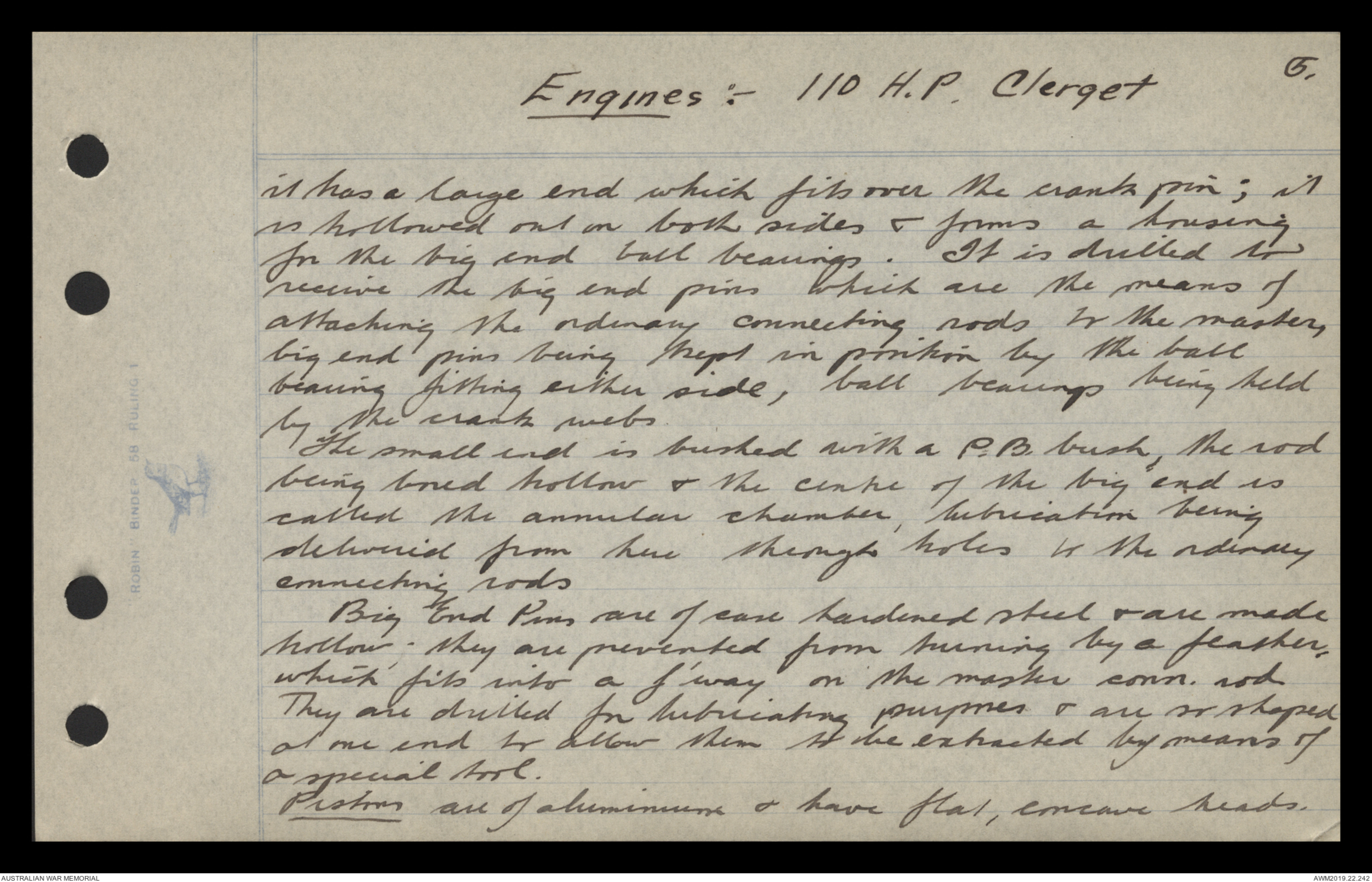
it has a large end which fits over the crank pin; it
is hollowed out on both sides & forms a housing
for the big end pins which are the means of
attaching the ordinary connecting rods to the master,
big end ball pins being kept in position by the ball
bearing fitting either side, ball bearings being held
by the crank webs.
The small end is brushed with a P.B. brush, the rod
being bored hollow & the centre of the big end is
called the annular chamber, lubrication being
delivered from here through holes to the ordinary
connecting rods.
Big End Pins are the case of hardened steel & are made
hollow - they are prevented from turning by a feather,
which fits into a f'way on the master conn. rod
They are drilled for lubricating purposes & are shaped
at one end to allow them to be extracted by means of
a special tool.
Pistons all of aluminium & have flat, concave heads.
6.
Engines : - 110 H.P. Clerget.
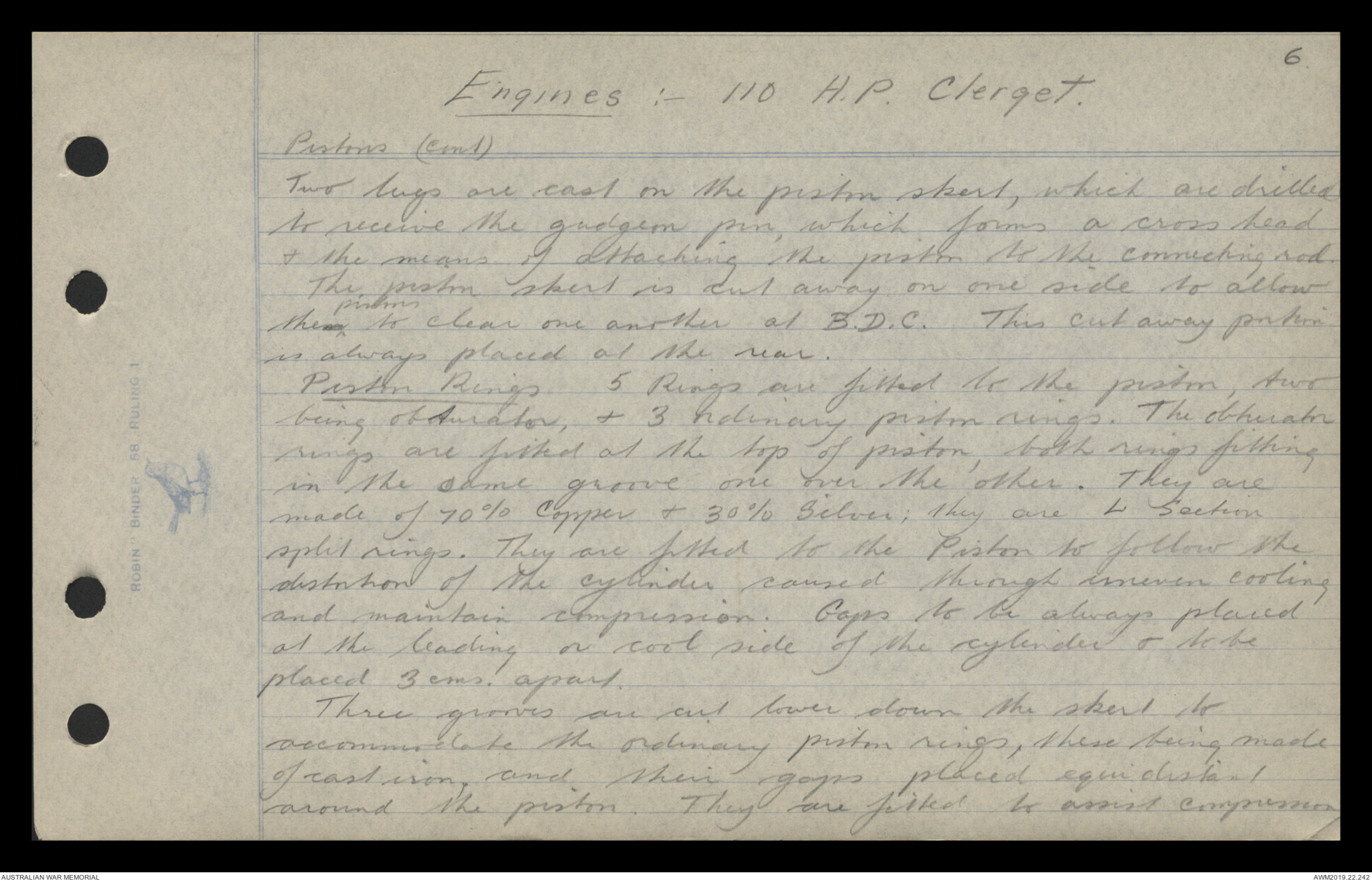
Pistons (cont)
Two lugs are cast on the piston skirt, which are drilled
to receive the gudgeon pin, which forms a cross head
& the means of attaching the piston to the connecting rod
The piston skirt is cut away on one side to allow
them ^ pistons to clear one another at B.D.C. This cut away piston
is always placed at the rear.
Piston Rings 5 Rings are fitted to the piston, two
being obturator, & 3 ordinary piston rings. The obturator
rings are fitted at the top of the piston, both rings fitting
in the same groove one over the other. They are
made of 70% copper & 30% silver; they are L section
split rings. They are fitted to the Piston to follow the
distortion of the cylinder caused through uneven cooling
and maintain compression. Gaps to be always placed
at the leading or cool side of the cylinder & to be
placed 3 cms. apart.
Three grooves are cut lower down the skirt to
accommodate the ordinary piston rings, these being made
of cast iron, and their gaps placed equidistant
around the piston. They are fitted to assist compression
 Jen
Jen This transcription item is now locked to you for editing. To release the lock either Save your changes or Cancel.
This lock will be automatically released after 60 minutes of inactivity.