Service notebook of Harold Gordon Cornell - 1917 - Part 5
Bombs.
spring & fire the detonator, & after ¼ sec. delay, the
main charge is fired.
Safety Devices:- (1) Transit Pin (2) Weak spring or Creep Spring.
(3) Safety Clip.
¼ Sec. Delay fuse for Pistol Tail (ext. of fuse, painted black)
When the detonator is fired, the gases are partially
checked by means of a delay screw, they then fire a
delay composition pellet. These two combined give a
¼ se. delay, then powder pellets are fired, which blow
out the end cap of the fuse & fire the main charge
Precautions Give wane ¾ turn
Clean spindle with petrol.
— Bombs. —
Nose fuse for 112 lb Bomb
Hand drawn diagram - see original document.
Hand drawn diagram - see original document.
Bombs
112lb. H.E.R.L Mk III
Loading:- Tail End. (1) Relay or instantaneous fuse
for conveying the gases from the tail end
of bomb down to the imploder.
(2) Pistol Tail Fuse (3) Pistol Tail
Nose End (1) H.E. Bomb long or exploder (2) Nose fuse
which is attached to the bomb by a G.S nut, the
latter being introduced to offer resistance when the
impact occurs.
H.E Bomb long or exploder consists of a cylinder of brass
containing H.E. & detonator is at either end, one fixed
the other loose. The loose detonator enables the
insertion of an extra washer if necessary. At the
fixed end is a silk end for withdrawing the bomb long
20lb. Cooper Bomb H.E
Description Cast steel case 5/16" inch thick, the tail
is made of wood, & carries 4 guiding vanes. The bomb
is fired by a D.A. nose fuse
Action On release from the carrier, the propellor is
allowed to rotate which during 15-25 ft of fall,
completes 25 revolutions bringing the striker into line with
Hand drawn diagram - see original document.
— Bombs —
20 lb Cooper Bomb H.E
the detonator & the spindle of the propellor
On impact, the propellor is pushed in shearing a
copper wire & compressing the spring & forces the striker
on to the detonator which is then fired & in turn fires
the main charge.
Safety Devices: (1) Transit Cover (2) Locking Wire
(3) Copper Shearing Pin. (4) Creep Spring (5) Numerals on
Carrier Wheel.
To prepare the Bomb: (1) Unscrew transit cover,
(2) Unscrew fuse (3) Insert detonator in base end of bomb
(4) Replace fuse & place bomb in 20 lb. C.F.S. carrier,
seeing that the special Cooper attachment engages
with propellor, which prevents same from rotating
until released. (5) Before flight, cut transit locking
wire. (6) If the bomb is not placed immediately in
C.F.S., replace transit cover.
Bombs.
Bomb Sight C.F.S. 4 B
Is composes of three sights: a movable & fixed fore
sight, and a fixed back-sight forming a rt L. triangle
the use of which gives the number of feet to
release bomb before coming to target.
To use Sight:- attain the height from which you
intend to release bomb; register this height in feet
on scale; by means of a stop-watch note the time,
that any auxiliary object in line with your target
requires the pass between sights. line A to line B.
Alter the height on your scale to this new time
registered by the watch. Fly towards your target in
an up or down wind, maintaining the same height
speed and direction. Immediately the target appears
at the end of sight line A release the bomb.
To fix sight Sight is fastened to rt hand side of
fuselage, when the machine is in flying position,
it may be moved up or down, through a groove in the
rear fixing plate, or to & fro between along two brass
rods, so as to give best position for the pilot
Bomb Sight C.F.S 4 B.
Hand drawn diagram - see original document.
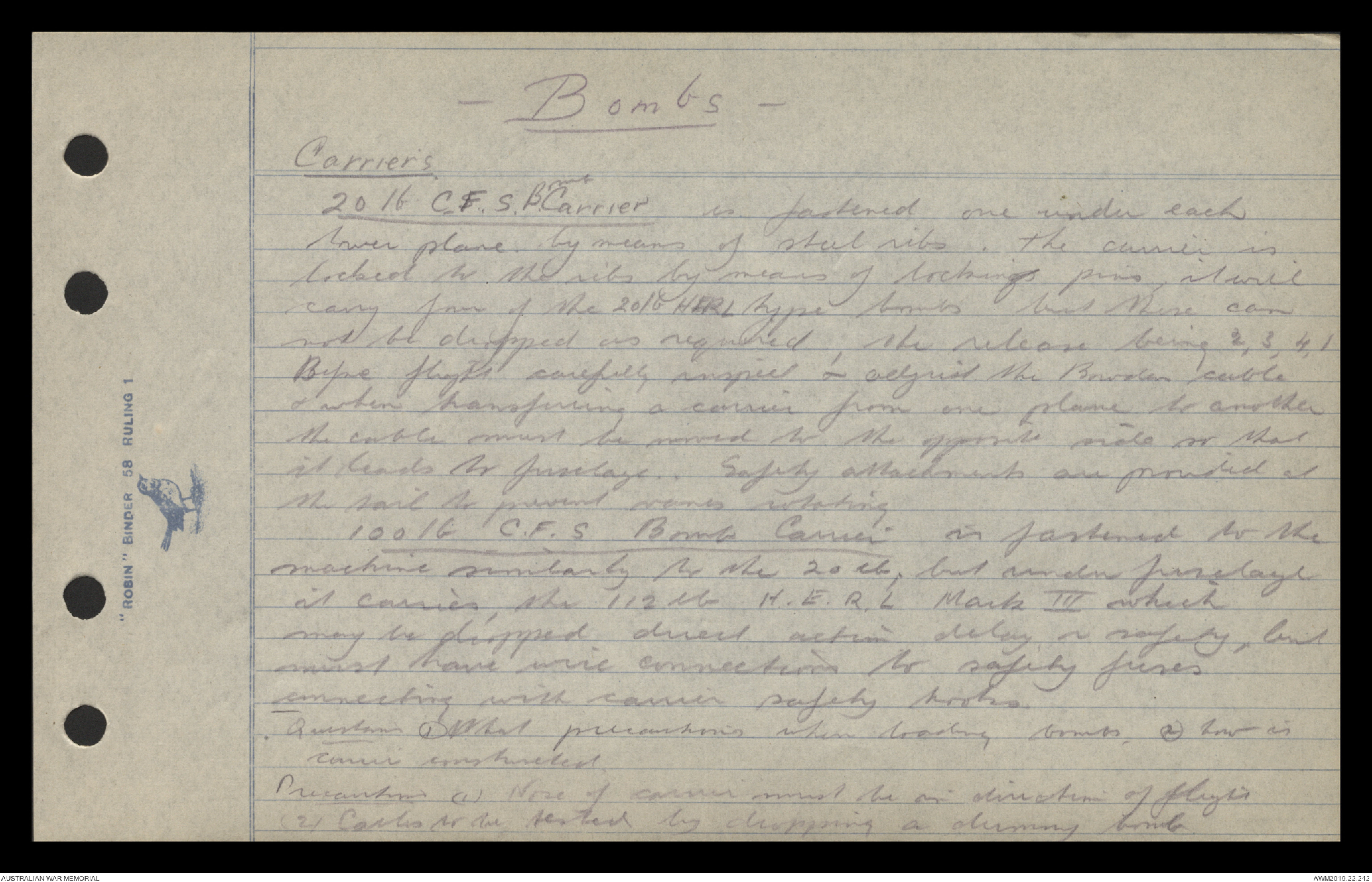
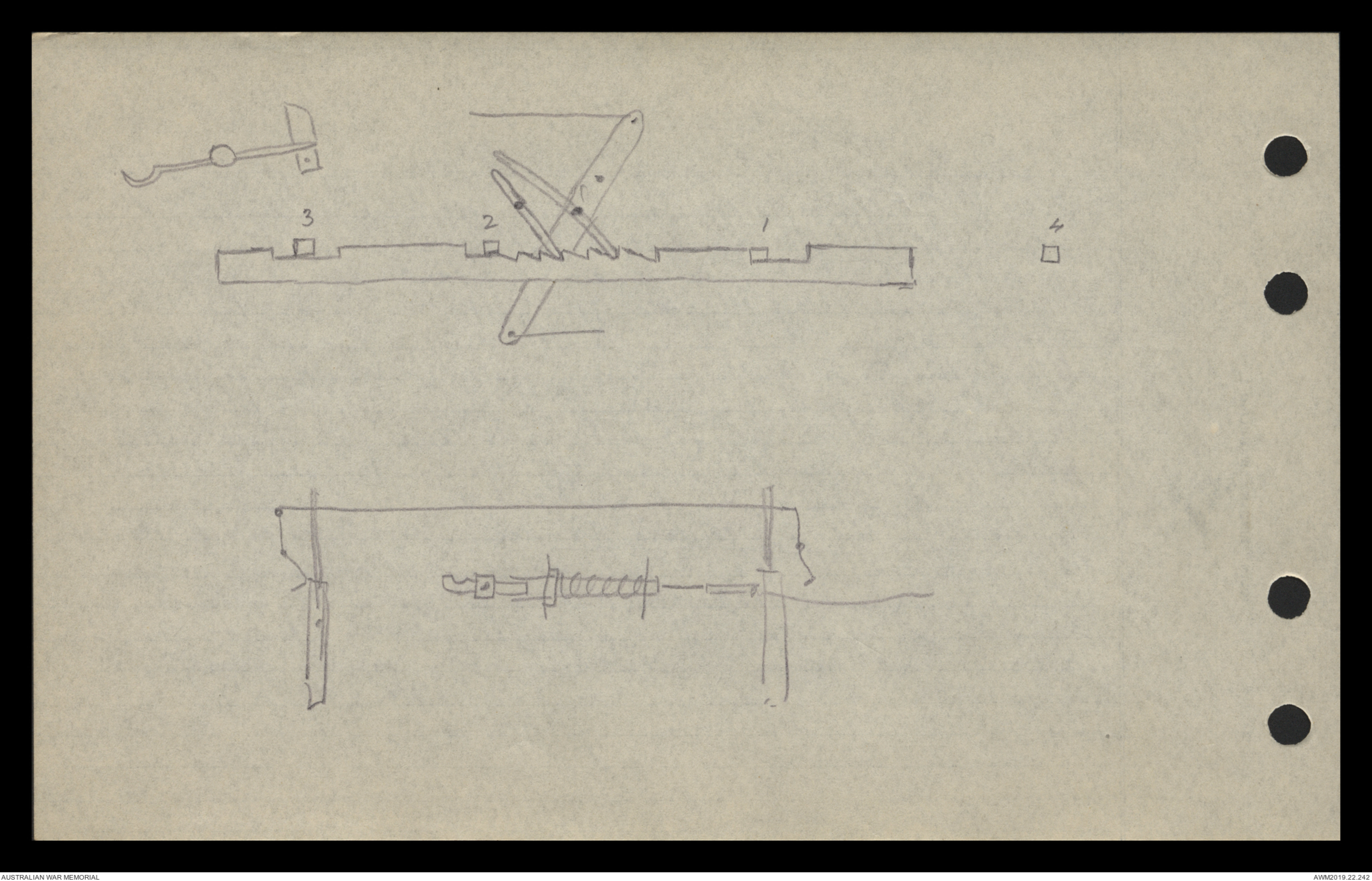
— Bombs —
Carriers
20 lb C.F.S. Bomb Carrier is fastened one under each
lower plane by means of steel ribs. The carrier is
locked to the ribs by means of locking pins, it will
carry four of the 20 lb HERL type bombs but these can
not be dropped as required; the release being 2, 3, 4, 1
Before flight carefully inspect & adjust the Bowden cable
& when transferring a carrier from one plane to another
the cable must be moved to the opposite side so that
it leads to fuselage. Safety attachments are provided at
the tail to prevent vanes rotating
100 lb C.F.S Bomb Carrier is fastened to the
machine similarly to the 20 lb, but under fuselage
it carries, the 112 lb H.E.R.L Mark III which
may be dropped direct action delay or safety, but
must have wire connections to safety fuses
connecting with carrier safety hooks.
Question (1) What precautions when loading bombs. (2) how is
carrier constructed
Precautions (1) Nose of carrier must be in direction of flight
(2) Cables to be tested by dropping a dummy bomb
Hand drawn diagrams - see original document
 Sam scott
This transcription item is now locked to you for editing. To release the lock either Save your changes or Cancel.
This lock will be automatically released after 60 minutes of inactivity.