Notebook of James Stuart Leslie Ross - Part 9


General Flying 13-7-17.
Lecture I
Cleaning. Parts to be kept clean on an
aeroplane:-
All Fabric, (Planes, Fuselage)
Never use petrol to clean fabric,
as it has a detrimental effect,
on dope & fabric
Greasing. Parts to be greased:-
All controls, turnbuckles, pulleys,
care to be taken that grease does
not come into contact with fabric
Painting Parts to be painted:-
All metals part struts or king
posts, or any parts that are likely
to rust.
Examination Points to look to:-
See that all turnbuckles are locked
All bolts must be split-pinned &
pins turned over.
Control Wires.
See that there is no fraying,
especially where wire goes over
pulley.
If forced landing is made & a stay
for some time is necessary, face
machine into wind & peg down
securely.
Inspection. Inspect all splices, tyres,
x under-carriage & tail skid.
See that all instruments are
O.K Examine rubber joints in
Air Speed Indicator tube
See that adjustable Aneroid Dial
is on O before going up.
General Flying Lec 2. 20.7.17
Don'ts
Dont fail to test controls.
" forget to switch off
" " " test engine
" take machine into air with
erratic Revs.
" taxi clear of sheds until
"all clear" signal given
" take off unless dead into
wind.
" baulk machines landing
" Stall.
" Choke engine getting off
" lose engine.
" circuit the wrong way
(Red flag right, blue flag left).
" depend on T
" turn without banking.
" forget that machine is frail
" " " the speed is greater
than it seems.
Theory of Flight 28.7.17
Flight is secured by driving a surface
up thro air upwards & towards
direction of flight.
Depends on.
(I) Forward Motion
(2) Size & Shape of Surface
(3) Angle of Incidence
Reaction caused by driving thro'
air.
R=KS V2 i
R = Reaction
K = A constant found by experiment
S Surface in Sq metres
V Velocity
i Is angle of incidence measured
in radians.
If speed is doubled, reaction of on
planes is 4 times as much as before.
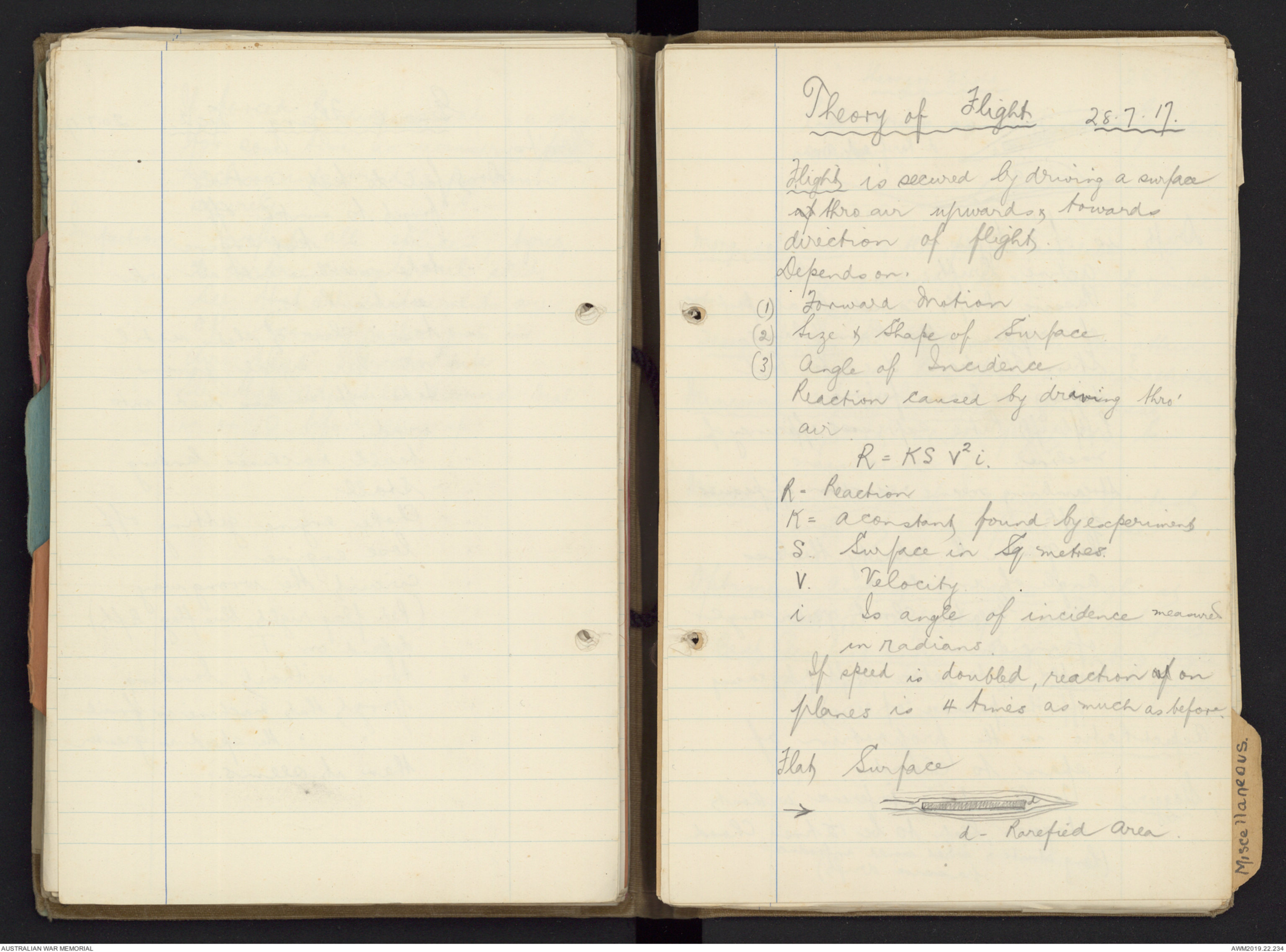
Flat Surface
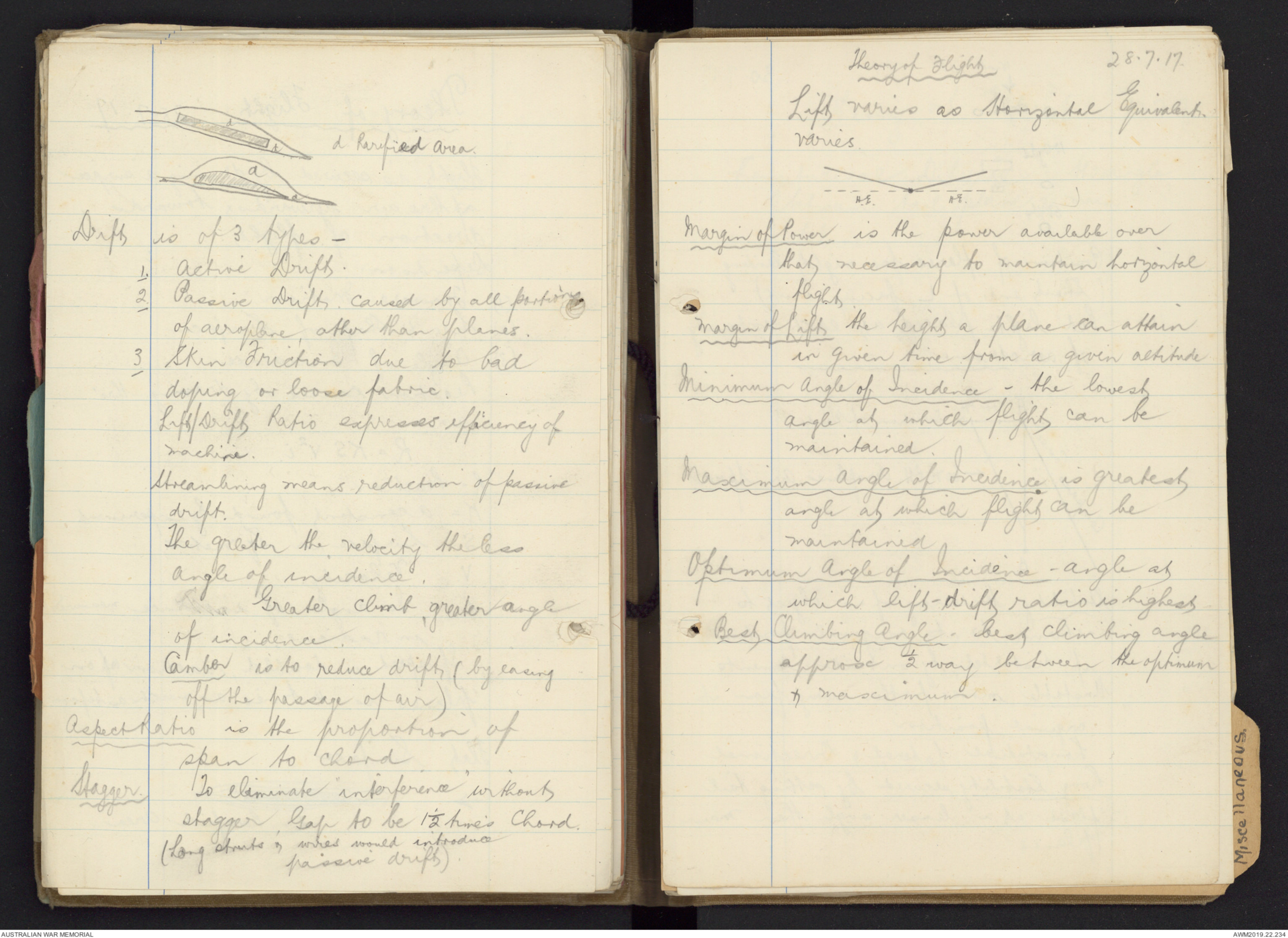
Hand drawn diagram - see original document
Hand drawn diagram - see original document
Drift is of 3 types -
1. Active Drift.
2. Passive Drift caused by all portions
of aeroplane, other than planes.
3 Skin Friction due to bad
doping or loose fabric.
Lift/Drift Ratio expresses efficiency of
machine.
Streamlining means reduction of passive
drift.
The greater the velocity the less
Angle of incidence.
Greater climb, greater angle
of incidence.
Camber is to reduce drift (by easing
off the passage of air).
Aspect Ratio is the proportion of
span to chord
Stagger To eliminate interference without
stagger. Gap to be 1½ times Chord.
(Long struts & wires would introduce
passive drift).
Theory of Flight 28.7.17
Lift varies as Horizontal Equivalent
varies.
Hand drawn diagram - see original document
Margin of Power is the power available over
that necessary to maintain horizontal
flight.
Margin of Lift the height a plane can attain
in given time from a given altitude
Minimum Angle of Incidence - the lowest
angle at which flight can be
maintained.
Maximum Angle of Incidence is greatest
angle at which flight can be
maintained
Optimum Angle of Incidence - angle at
which lift-drift ratio is highest
Best Climbing Angle - best climbing angle
approx ½ way between the optimum
& maximum.
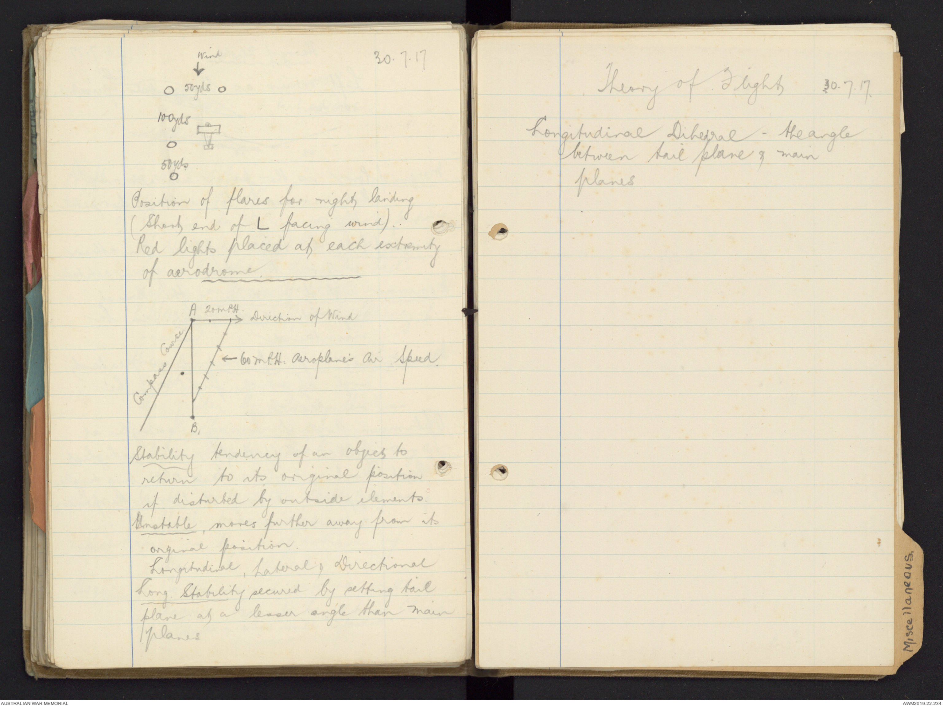
30.7.17
Hand drawn diagram - see original document
Position of flares for night landing
(Short end of L facing wind).
Red lights placed at each extremity
of aerodrome.
Hand drawn diagram - see original document
Stability tendency of an object to
return to its original position
if disturbed by outside elements
Unstable moves further away from its
original position.
Longitudinal, Lateral, Directional
Long Stability secured by setting tail
plane at a lesser angle than main
planes
Theory of Flight 30.7.17
Longitudinal Dihedral - the angle
between tail plane & main
planes
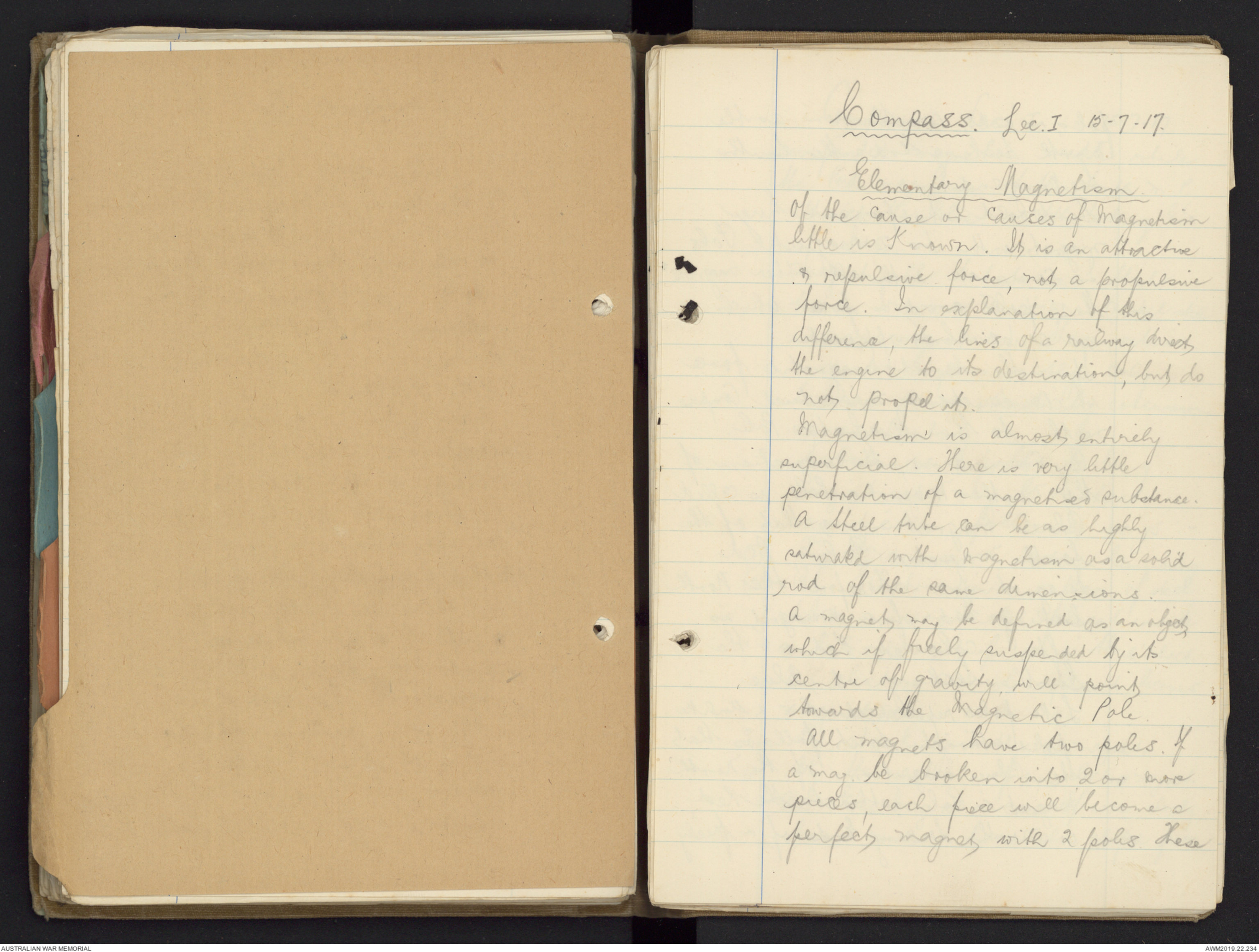
Compass. Lec. I 15.7.17.
Elementary Magnetism
Of the cause of causes of magnetism
little is known. It is an attractive
& repulsive force, not a propulsive
force. In explanation of this
difference, the lines of a railway direct
the engine to its destination, but do
not propel it.
Magnetism is almost entirely
superficial. There is very little
penetration of a magnetised substance.
A steel tube can be as highly
saturated with magnetism as a solid
rod of the same dimensions.
A magnet may be defined as an object
which if freely suspended by its
centre of gravity, will point
towards the Magnetic Pole.
All magnets have two poles. If
a mag. be broken into 2 or more
pieces, each piece will become a
perfect magnet with 2 poles. These
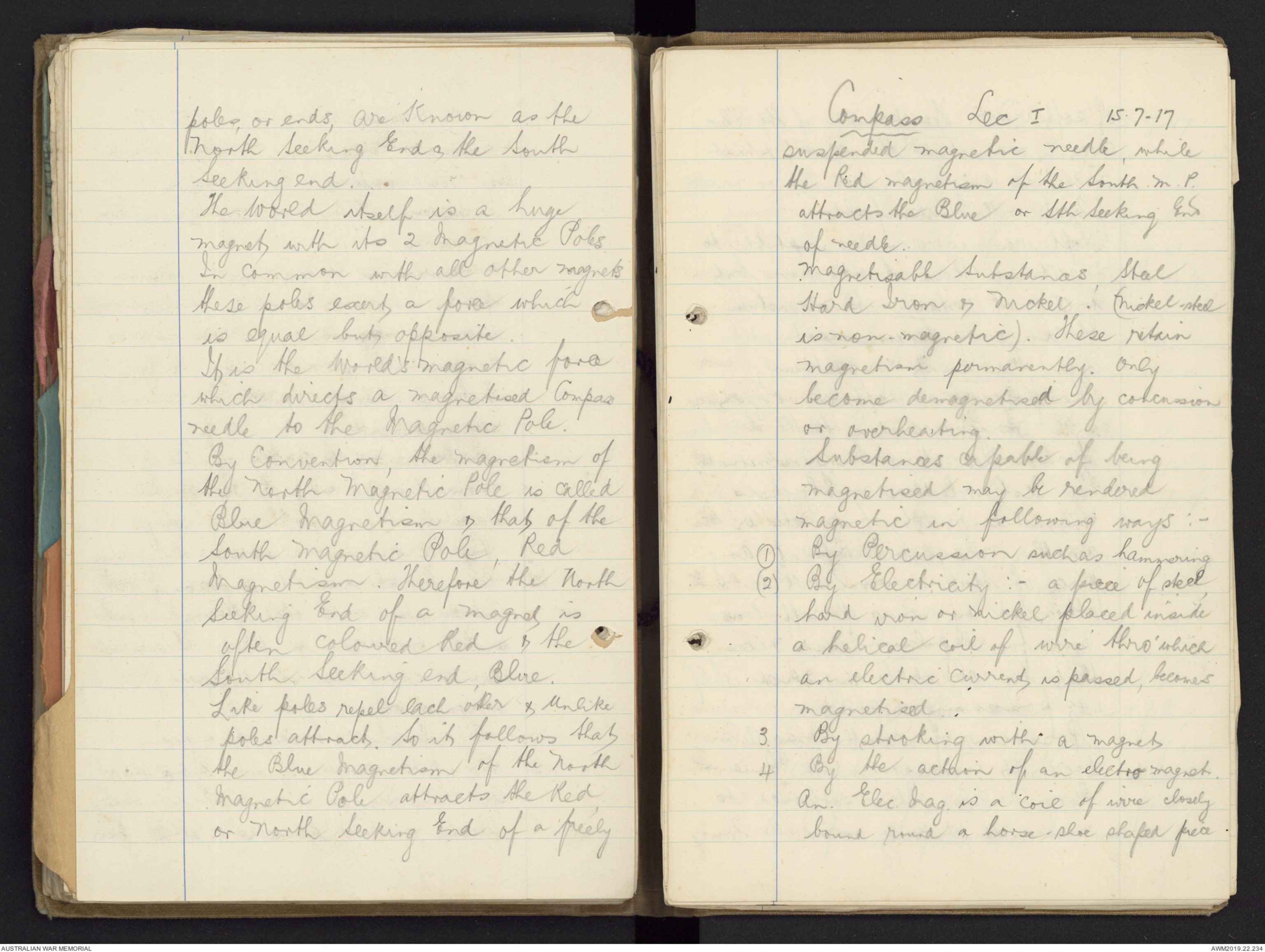
poles, or ends, are known as the
North Seeking End & the South
Seeking end.
The World itself is a huge
magnet with its 2 Magnetic Poles.
In common with all other magnets
these poles exert a force which
is equal but opposite.
it is the World's magnetic force
which directs a magnetised Compass
needle to the Magnetic Pole.
By Convention, the magnetism of
the North Magnetic Pole is called
Blue Magnetism & that of the
South magnetic Pole, Red
magnetism. Therefore the North
Seeking End of a magnet is
often coloured Red & the
South Seeking end, Blue.
Like poles repel each other & unlike
poles attract. So it follows that
the Blue Magnetism of the North
Magnetic Pole attracts the Red
or north Seeking End of a freely
Compass Lec I 15.7-17
suspended magnetic needle, while
the Red magnetism of the South M.P.
attracts the Blue or Sth Seeking End
of needle.
Magnetisable Substances, Steel
Hard Iron & Nickel. (Nickel-steel
is non-magnetic). These retain
magnetism permanently. Only
become demagnetised by concussion
or overheating.
Substances capable of being
magnetised may be rendered
magnetic in following ways :-
(1) By Percussion such as hammering
(2) By Electricity :- a piece of steel,
hard iron or nickel placed inside
a helical coil of wire thro' which
an electric current is passed, becomes
magnetised.
3. by stroking with a magnet
4. by the action of an electromagnet.
An Elec. Mag. is a coil of wire closely
bound round a horse-shoe shaped piece
of soft iron. The passage of the elec.
current magnetises this core, which
magnetises any steel, hard iron or nickel
placed within its field.
Soft iron is more susceptible to
magnetism than hard iron but
will not retain its magnetism.
it can only become saturated
with Transient magnetism.
The poles of a soft iron object
will vary according to the direction
from which it is being magnetised.
To test whether an object is
magnetic or not, find whether
another mag. will repel it. Any
piece of Steel or iron will be
attracted by a mag. of suff. Power.
But for Repulsion it is necessary
that the object be magnetised itself
& so possessing 2 poles.
Position of North Mag. Pole
does not correspond with True or
Geog. N. Pole. It is supposed to
move elliptically round the True
Compass Lec I 15-7-17.
North. It is now moving slowly
Eastward. It is situated over 1000
miles South of the true pole, to
the westward of it, so the Magnetic
Meridian does not correspond with
the Geog. Meridian. The 2 Meridians
drawn from Greenwich contain an
angle of 15°. This is Known as
Mag. Variation.
The force exercised by Magnetism
has 2 Components - a Horizontal &
a Vertical but as in the manuf. of
compasses the vert. component is
compensated for mechanically. It
is not necessary to deal with these
components in a brief treatise
devoted to Elem. Magnetism.
All Compasses work on
exactly the same principle,
no matter how they may vary in
construction. With the exception
of the magnetised needles all parts
of a compass are non-magnetic.
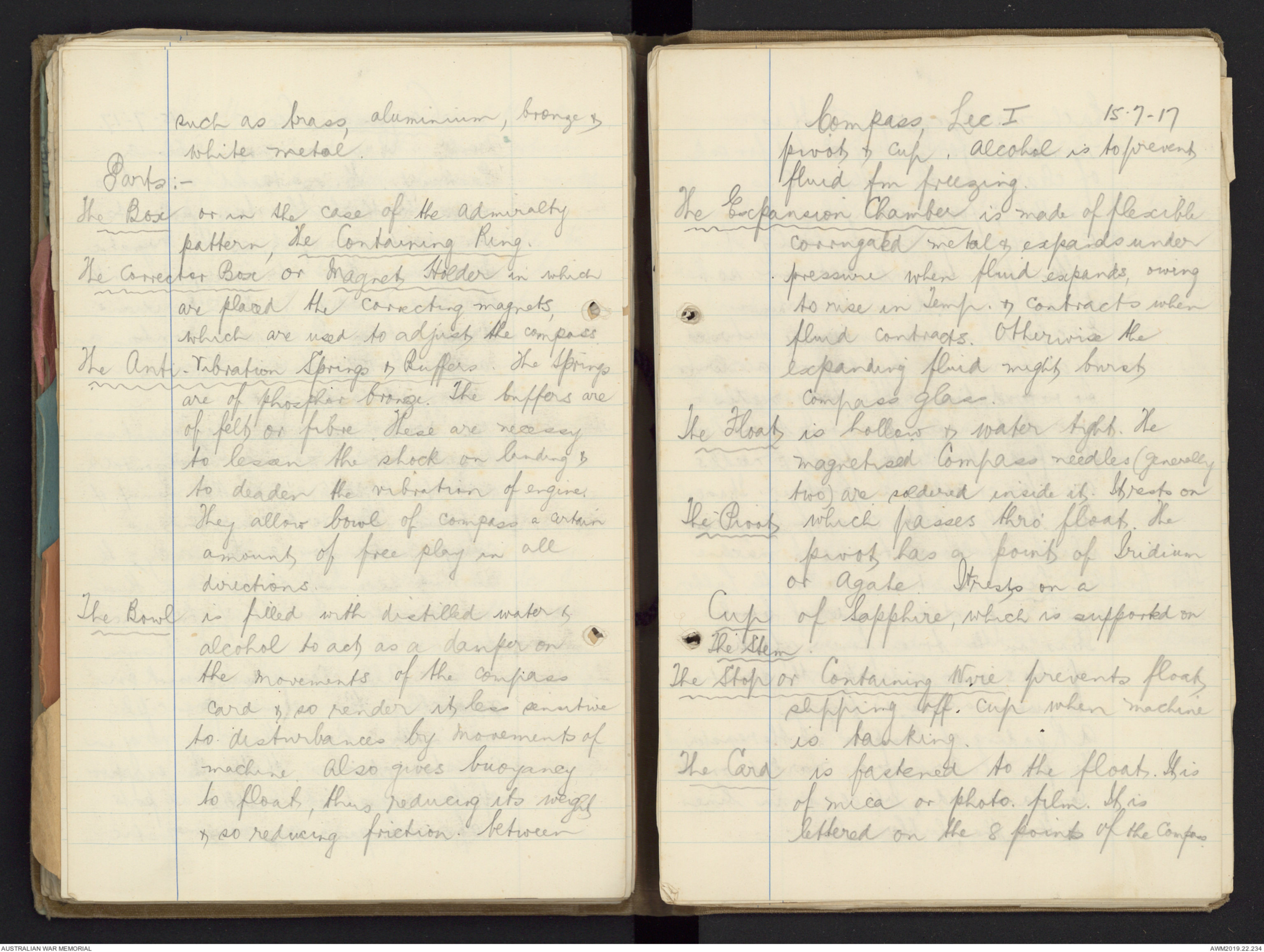
such as brass, aluminium, bronze &
white metal.
parts:-
The Box or in the case of the admiralty
pattern, the Containing Ring.
The Corrector Box or Magnet Holder in which
are place the correcting magnets,
which are used to adjust the compass.
The Anti-Vibration Springs & Buffers. The Springs
are of phosphor bronze. The buffers are
of felt or fibre. These are necessy
to lessen the shock on landing &
to deaden the vibration of engine.
They allow bowl of compass & certain
amounts of free play in all
directions.
The Bowl is filled with distilled water &
alcohol to act as a damper on
the movements of the compass
card & so render it less sensitive
to disturbances by movements of
machine. Also gives buoyancy
to float, thus reducing its weight
& so reducing friction between
Compass Lec 1
15-7-17
pivot & cup. Alcohol is to prevent
fluid from freezing.
The Expansion Chamber is made of flexible
corrugated metal & expands under
pressure when fluid expands, owing
to rise in Temp. & contracts when
fluid contracts. Otherwise the
expanding fluid might burst
compass glass.
The Float is hollow & water tight. The
magnetised Compass needles (generally
two) are soldered inside it. It rests on
The Pivot which passes thro' float. The
pivot has a point of Iridium
or Agate. It rests on a
Cup of Sapphire, which is supported on
The Stem.
The Stop or Containing Wire prevents float
slipping off cup when machine
is banking.
The Card is fastened to the float. It is
of mica or photo. film. It is
lettered on the 8 points of the Compass.
Each marking rep 5°. It is
numbered for every 10° but for sake
of clearness the cypher 0 is
omitted; for example,
E, which is 90° is numbered 9. It is
often painted with radium so that
it may be read in the dark.
Except when momentarily disturbed
by a turn or by engine acceleration,
or retardation, the mag. needles
are continually pointing to the North,
therefore the card, float & needles
are practically a fixture. It is only
the bowl & outer case of Compass
which follow turns of machine.
The Lubber Line sometimes called the Lubber
point is fixed to the inside of bowl.
It is in the true fore & aft line
of bus & so indicates the direction
in wh. machine is flying.
A Reading of Compass is the register of
the particular degree, marked on the
compass card, which is in line
with the lubber line
Compass Lec 2. 22-7-17
Deviation the horizontal angle contained
between the compass & magnetic
meridians
Variation the horizontal angle [[?]] between the
direction of the magnetic & true
meridians
Correcting for Deviation
to correct for an error on North
or South place correcting magnets
East & West
To correct for an error on East
& West, corrector magnets must be
placed East is West because the
Corrector magnets must always
be placed across the compass
needle (machine turned East)
 Marisa Bortolotto
This transcription item is now locked to you for editing. To release the lock either Save your changes or Cancel.
This lock will be automatically released after 60 minutes of inactivity.