Notebook of James Stuart Leslie Ross - Part 8

Rigging Lecture III. 14.7.17
Sail Making.
How to Mend a Bullet or Shrapnel
Hole in a Plane.
First cut out all bad parts in
shape of a Square. Cut each corner
¼" diagonally, turning in edges
¼". Cut a patch ¼" bigger all
round, turning in edges ¼", sewing
patch with an under & over stitch.
Clean around patch with acetone.
Cut a second patch an inch
bigger all round, with frayed
edges. Stick second patch on top
of sec first with dope. To finish
apply 2 coats of dope & 1 of varnish.
To Mend a Slit or Tear
Draw tear together with under
& over stitch. Clean round
stitching with acetone. Stick a
patch 1 inch wide over stitching
& a second patch of 2" wide
with frayed edges & finish with
2 Coats of dope & one of varnish
Dope, Uses of.
Waterproofing, Strengthening,
adhesive purposes, tautness &
renders the plane airtight.
Never apply less than 5 Coats
of dope & 2 of varnish to a
new plane.
Plane, Covering of
Before covering, see that all
turnbuckles are safely locked.
Joining 2 pieces of fabric &
Hand drawn diagram - see original document
sew Seams.
Air holes in under side trailing
edge to give ventilation to interior.
To Keep camber in planes, string
ribs.
To ascertain whether plane needs
re-doping, apply finger test.
Rigging Lec III 14-7-17
Directions for Wire Splicing with English
"Tuck" Splice.
1 Bind wires with thread for 2in at distance
of 6in from end & shape loop & secure.
2. Separate Strands & bind ends.
3 Find ''heart'' wire & put thro' the centre of
cable & secure loose end.
4. Hold cable with loose ends pointing away &
downwards & take lowest strand on right
& pass it under strand on right of
'heart' wire.
5. Work from right to left.
6 Enter No 2 wire where No 1 comes out,
& pass under one strand & pull out.
7 Repeat with Nos 3 & 4, entering them
where previous wire comes out.
8 Enter No 5 where No.4 comes out & pass
under two strands, coming out where No 1
entered.
9. Enter No 6 in the same place as No 5,
i.e where No 4 comes out, but pass under
one strand only.
10 First round completed, one wire will come
out at each space it is not now
necessary to place No 5 wire under 2 strands
as in the first round.
11 Repeat for 3 strand rounds over one
strand & under one & always bury
"heart" wire.
12 Always pull wire tight & beat into
shape after finishing each round.
13 After completing 3 rounds take Nos 1, 3 & 5
wires & pass them over one strand &
under two.
14 Cut off ends & bind with thread
(the binding should not be more
than 1in long).
Rigging. Lecture 4. 15-7-17.
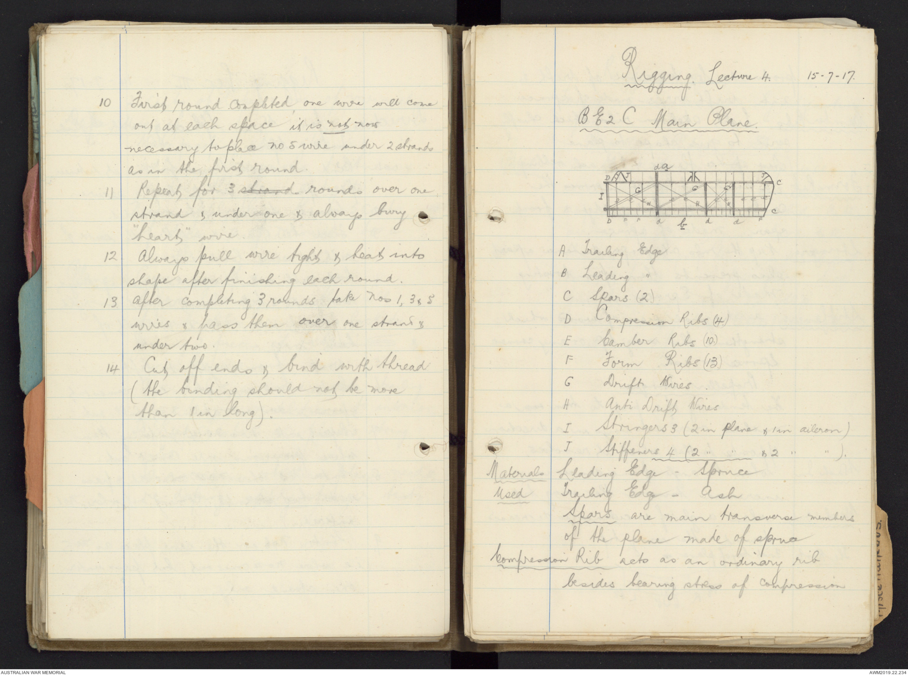
BE2C Main Plane.
Diagram - see original document
A Trailing Edge
B Leading "
C Spars (2)
D Compression Ribs (4.)
E Camber Ribs (10.)
F Form Ribs (13.)
G Drift Wires.
H Anti Drift Wires
I Stringers 3 (2 in plane & 1 in aileron)
J Stiffeners 4 (2 " " & 2 " " ).
Materials Leading Edge - Spruce
Used Trailing Edge - Ash
Spars are main transverse members
of the plane made of spruce
Compression Rib acts as an ordinary rib
besides bearing stress of compression
produced by tension of drift &
anti-drift wires - made of spruce.
Camber Ribs - Light skeleton ribs which chiefly
serve to give shape to plane
(Have spruce flanges & 3-ply ash webbing).
Form Rib - a small rib which improves the
camber between leading edge & front
spar. Made of spruce.
Stringers Keep the ribs at proper distance apart,
also prevents them from twisting
made of Spruce.
Stiffeners a diagonal piece of wood which
strengthens the wing tip or any corner.
Spruce or ash.
Propeller Torque.
The tendency of a prop to turn over a
machine over side ways in a direction
opposite to that which it revolves.
Wash In. when the angle of incidence is
increased toward the wing tip
Wash Only when angle of incidence is decreased
toward the wing tip
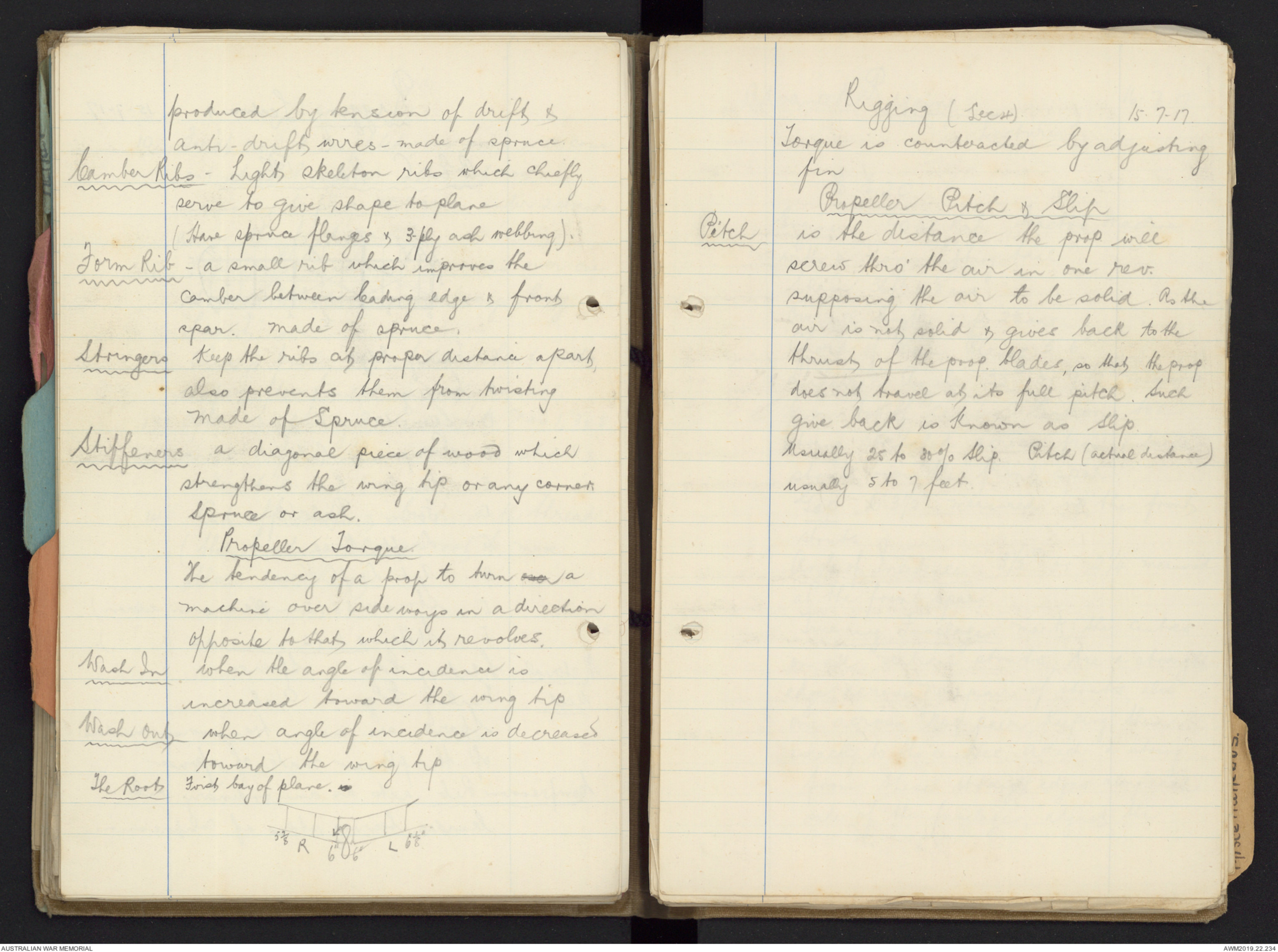
The Root First bay of plane. is
Hand drawn diagram - see original document
Rigging (Lec 4) 15.7-17.
Torque is counteracted by adjusting
fin
Propeller Pitch & Slip
Pitch is the distance the prop. will
screw thro' the air in one rev.
supposing the air to be solid. As the
air is not solid & gives back to the
thrust of the prop. blades, so that the prop
does not travel at its full pitch. Such
give back is known as Slip.
Usually 25 to 30% Slip. Pitch (actual distance)
usually 5 to 7 feet.
Advanced Rigging 16.7.17.
Lecture 5.
B.E.2C.
Engine 90 H.P Raf. Tractor Machine
with a non-lifting tail.
Span 36 ft 11 1/8 ins
Overall length 27 ft 2½ ins.
Chord of Main Planes 5' 6".
Dihedral Angle 3½° or 9½" measured
from top of centre Section to a
string stretched across from outside
struts over the front spar
Gap 6' 3½" measured up the front
struts
Angle of Incidence 3½° or 2¼" measured
at the front spar
True-ing Fuselage. mark the centres
on all vertical struts, tie a straightedge
across No 1 pair of struts, also
one across No 9 pair, Keeping them
exactly to the centres. Attach a string
from these straights edges along each
side of the fuselage, adjust the
internal bracing rods getting them an equal
length in pairs. Adjust the side bracing rods
to make the centres correspond with the string.
No 4 centres should be 3/16". below the line
Trueing the Centre Section.
Adjust the drift & anti-drift wires to make
the Struts vertical from side view.
Adjust the C.S. bracing wires getting
them an equal length
Trueing the Under Carriage (V Type).
The U.C. bracing wires should be an equal
length.
To Assemble a Set of Main Planes.
Place the planes on their leading edges,
fix interplane struts, stagger wires,
landing & flying wires of the outer bay
To True the Dihedral
Adjust the front landing sending
& flying wires getting them an equal
length in pairs
To adjust the Angle of Incidence
Adjust the back landing & flying
wires working the Stagger wires in conjunction.
The Stagger 24 inches, adjusted by stagger wires
Rigging (Lec.5.)
The Angle of the Tail Plane 3½° adjusted
on No 10 Vernier struts
Adjustment of Controls The Ailerons should droop
5/8".
To Adjust Rudder Fix the foot control
Square across fuselage, adjust the control wires
so that the rudder points directly backwards
To Adjust Elevators. Fix the control lever
6° forward, adjust the control wires so that
the elevators continue a straight line of the
tail plane.The fin placed central.
Engine Cowling. Covering the engine.
The Combing Covering for fuselage.
The Fairing for stream line effect.
The Centre Section Struts are made of steel
tubing, covered with wood fairing &
bound with fabric
Diagram - see original document
(Lec.6. 17.7.17).
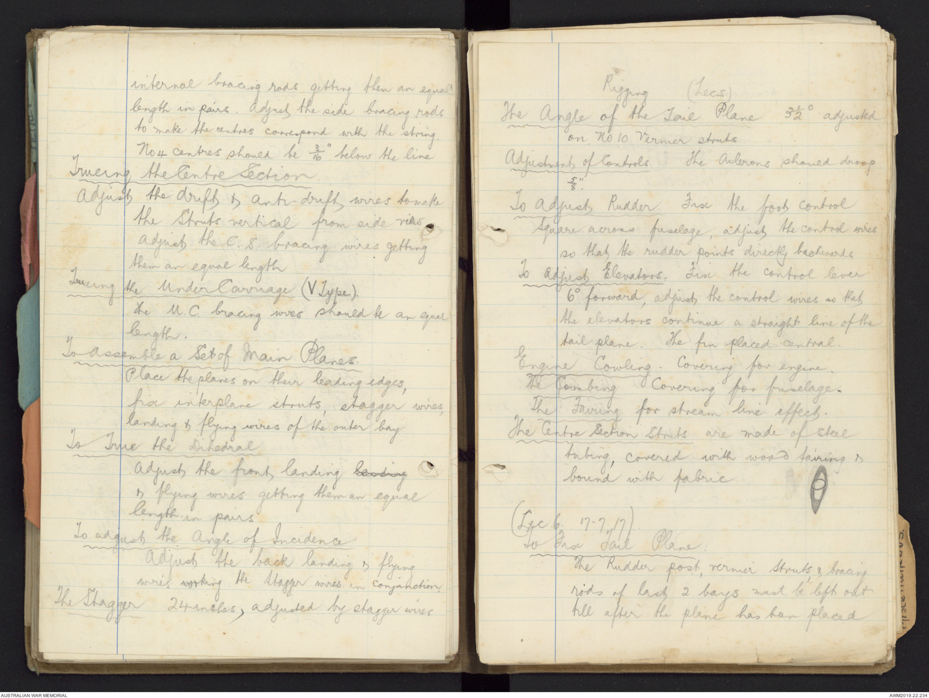
To Fix Tail Plane:
The Rudder post, vernier Struts & bracing
rods of last 2 bays must be left out
till after the plane has been placed
in position
Diagram - see original document
BE2C Tail Plane has 4 Compression tubes
(not ribs not being in Compression)
Tail Plane has internal bracing rods -
not called drift & anti drift wires as
in main planes.
When trueing fuselage work from
front to rear.
A Lifting Tail would have an angle
of incidence & be either cambered
or straight underneath.
A Non-Lifting Tail is same both sides,
& streamlined with air currents
Transverse Bracing on BE2C is made of ash
Rigging Lecture 6. 22-7-17
FE2B.
Engine 120 HP Beardmore
Speed 76 miles p.h. (average)
Nacelle To True up.
Place machine in flying position -
Engine bearers, bottom longerons &
rear transverse struts level.
Mark the centres of the first & last
pair of vertical struts. Place
straight edges across & adjust internal
& side bracing rods until straight
edges are parallel sighted from the
front. Trammel all transverse bays.
Materials Bottom longerons & engine bearers
are ash.
Top longerons & all other struts are spruce
Under Carriage "Oleo" Type
Constructed of steel tubing, covered
with fairing. The shock of landing
is taken on the rear struts which
are telescopic with a spiral spring
fitted at the top. A small wheel
in front is mounted on 3 steel. booms
supported to the nacelle by 2 pairs of
V struts. Connecting the rear V struts to the
axle are 2 radius rods
To True up Undercarriage.
Drop a plumb line from leading edge
of bottom planes & adjust cross bracing
wires until the centre of axle is 2 7/8"
behind plumb line
Centre Section Assembling.
Place top centre plane on L.E. on ground,
fit struts (8.) (shortest at rear)
Lift up & bolt the 4 centre struts to
top longerons of Nacelle attaching
crossbracing, drift & anti drift wires
to hold in position. Fit the 2 lower
sections & wire up
To True Up. First trammel crossbracing
wires & adjust front landing & flying
wires until leading edge of top plane is
straight. Adjust rear landing & flying
wires for incidence. Stagger Nil
Main Planes Dihedral 4° or 10.85 inches measured
at each end of Centre Section
Rigging Lec 6. (Contd) 22.7.17
Angle of Incidence is 4° 9" or 2¼" from centre
of rear spar to centre of front spar.
Ailerons droop 5/8"
Rigging Lec 7 23.7.17
Tail Sections Assembling outrigger
Lie the top & bottom booms of one
side on the ground (top boom is
longer) fit struts & side bracings.
Do the same with other side. Lift
both sides upright & fit transverse
struts & internal bracing wires
The Skid is fitted to lower rear transverse
strut. Now fit rudder post & rudder
(Rudder post is double, the Inner tube acting
as a strut, the outer tube, to which
rudder is mounted runs on ball-bearings
on the inner tube). Lift outrigger
up & bolt to Centre Section
To True Up.
First trammel internal bays
Adjust side bracing wires making lower
booms level & straight in flying
position. Side struts vertical, top booms
straight.
Tail Plane is non-lifting. Stream line section.
Fitted to top of top booms. The front
spar pivoted x, rear spar is attached
to a vernier scale from which
adjustments may be made.
To True Tail Plane
Adjust on vernier scale until the
distance between the under side of
rear spar & the top of top booms
is 3½". This equals an angle of 3¾°.
(This is for trial flight). Bolt the
fin on top of tail plane & adjust
top & bottom tail bracing wires
making tail plane horizontal & fin
vertical. Fin is set central
Materials Used. Tail booms are hollow spruce.
All Struts are solid spruce
Fin & rudder are of steel
Tail Plane Spruce with 4 steel
Compression tubes
16-7-17.
Materials used in Aeroplane
Construction.
Wire is always used where there is tension
Wood " " " " " " Compression
Chief Woods Used :-
Spruce, Ash, Mahogany & Walnut
These combine lightness & strength.
Spruce, light & tough, very straight
grain, no Knots & very tough
under compression. Used in Main
Members of fuselage (longerane).
Ash. is very light & Strong & has "whip".
Used for Spars & struts & nearly
always for undercarriage
Walnut & Mahogany are used in
props.
All wood should be treated with
shellac varnish. This gives a polish
to wood.
Wires Piano Wires are always used where
there is an even stress && never
never used when there is an uneven
strain. (Now being superseded by
RA.F. Wires). which increase speed 6 - 8 MPH.)
Cables always give warning when about
to break. Is flexible & is used
for control wires
Framework of Machine Covered with
Fabric. light & strong linen &
secured to framework by small
brass tacks or threaded to
Spars etc.
Dope. placed on fabric for purposes of
tightening & for waterproofing. If
painted with RA.F paint leave
off 2 Coats of dope.
Woods. Ash flexible, very tough & resists
Properties of a sudden strain. Is used in
undercarriage (largely)
Bamboo Liable to split, is light & strong
Used in Tail booms of a Pusher
as an F.E.
Beech strong & close-grained, not durable
if exposed.
Birch strong, close grained & non -
splitting
Cedar stands exposure used as veneer
Materials Used in Aeroplane
Construction. 16-7-17.
Elm durable, tough, stiff & strong but
warps
Hickory Strong, tough & non-splitting.
Durable if varnished, sometimes
used as a tail-skid.
Mahogany liable to split & does not stand
exposure
Maple Light & non-splitting.
Oak very strong but too heavy
Poplar is durable, tough & very light
Walnut is light, tough, but brittle.
Teak compact, uniform quality & very
durable.
 Marisa Bortolotto
This transcription item is now locked to you for editing. To release the lock either Save your changes or Cancel.
This lock will be automatically released after 60 minutes of inactivity.