Notebook of James Stuart Leslie Ross - Part 7


quarter open, ignition lever
retarded & main air intake ports
closed, then turn prop. round
several revs. to suck a good mixture
into cyls. always leaving the prop.
just over the compression stroke.
Then after being given "All clear"
switch on all magnetos & turn
small handle on C.A.V. until
engine is started. After engine
is started switch off the C.A.V.
& run engine about 600 revs p.m.
until engine is warmed up.
Carburettors There are 2 Carbs. which are
Beardmore design & water-jacketed,
each one supplying 3 cyls. They are
each made with a single jet, the
control being by means of a rotary
sleeve which is so designed to
keep the ratio of petrol & air constant
at all speeds of engine.
Tracing Petrol thro' Carburetter
The petrol is forced by pressure
Beardmore (Lec 6. Contd.)
from the main tank into the filter,
up the needle valve into the circular
float chamber, float rises against
balance weights & cuts off the
supply when the petrol reaches its
proper level. The petrol is drawn
out of the jet & also air from
the main air inlet by suction from
the engine & is drawn thro' the choke
tube into the mixing chamber where
it mixes with the extra air from
the extra air inlet & is quickly
vaporised by the aid of hot water
round the jackets. From here it is
controlled by the rotary sleeve &
passes out in form of a vapour
thro' induction pipes & inlet valves
into cyls.
Tracing petrol from Tank to Exhaust
Petrol flows by pressure into carb.
thro' gauze filter into float chamber.
The float rises with petrol, thus closing
needle valve seating. The jet is in
communication with the chamber &
petrol rises to same level. Induction
occurs, sucks mixture thro' the choke
tube into mixing chamber where it
mixes with the extra air & is then sucked
thro' induction pipe into cyl. Ignition
occurs, fires mixture which passes
out as exhaust.
1 Water Circulation.
2 Carburettor.
3 Thrust.
4 Cam Angle Lever.
5 Lubrication (Description of Bosch pump not reqd).
Force, Splash & Grease.
Beardmore Lubrication.
Grease Cups. -
1 in each Rocker Arm.
1 " Spindle of Water Pump.
2 Cam & Crank Shaft gear wheels.
Sump - 6 Compartments. ¾ pints of
oil in each.
Made of aluminium alloy.
blank page - see original document
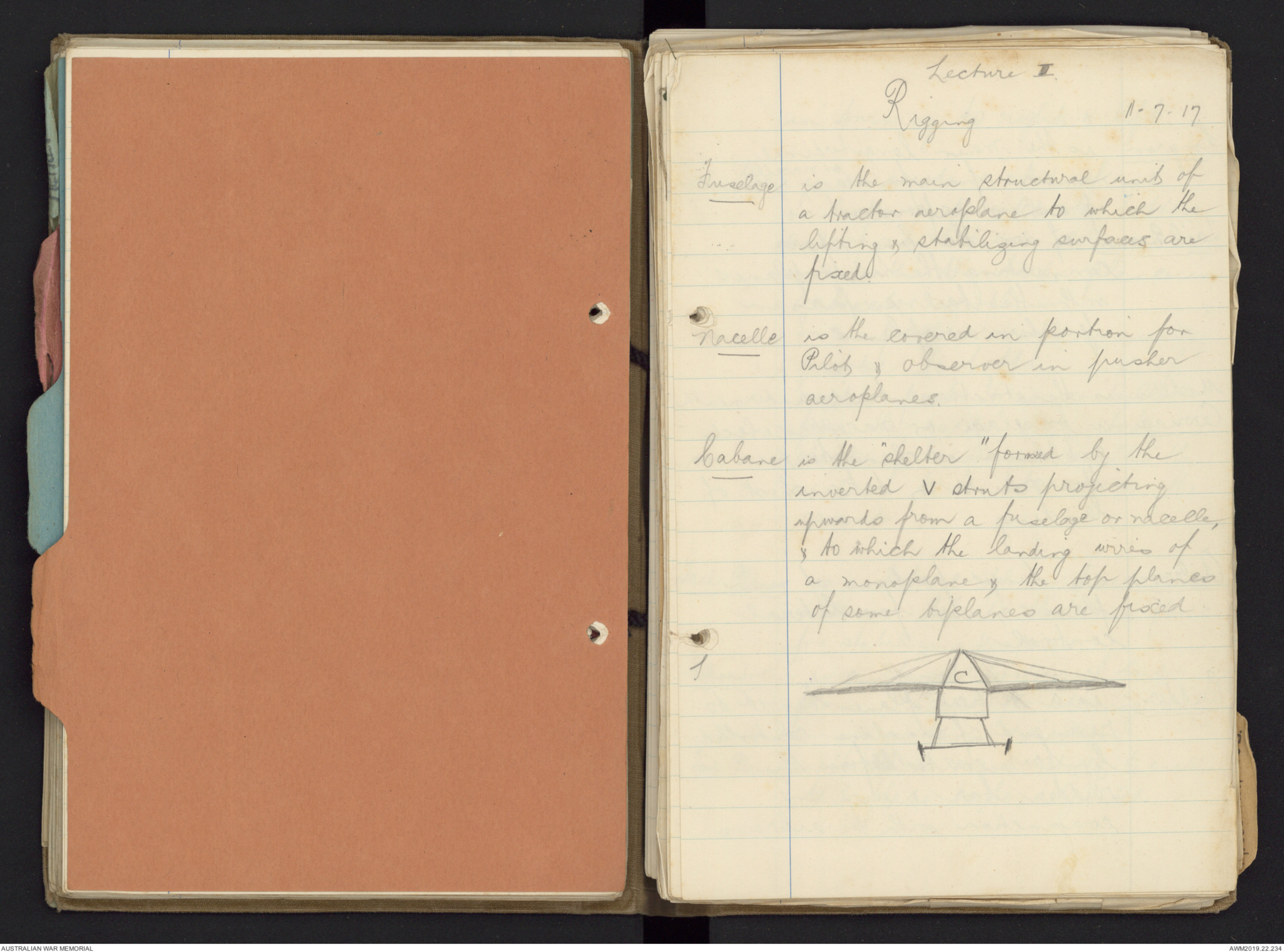
Lecture II
Rigging 11-7-17
Fuselage is the main structural unit of
a tractor aeroplane to which the
lifting & stablizing surfaces are
fixed.
Nacelle is the covered in portion for
Pilot & observer in pusher
aeroplanes.
Cabane is the "shelter" formed by the
inverted V struts projecting
upwards from a fuselage or nacelle,
& to which the landing wires of
a monoplane & the top planes
of some biplanes are fixed.
Hand drawn diagram - see original document
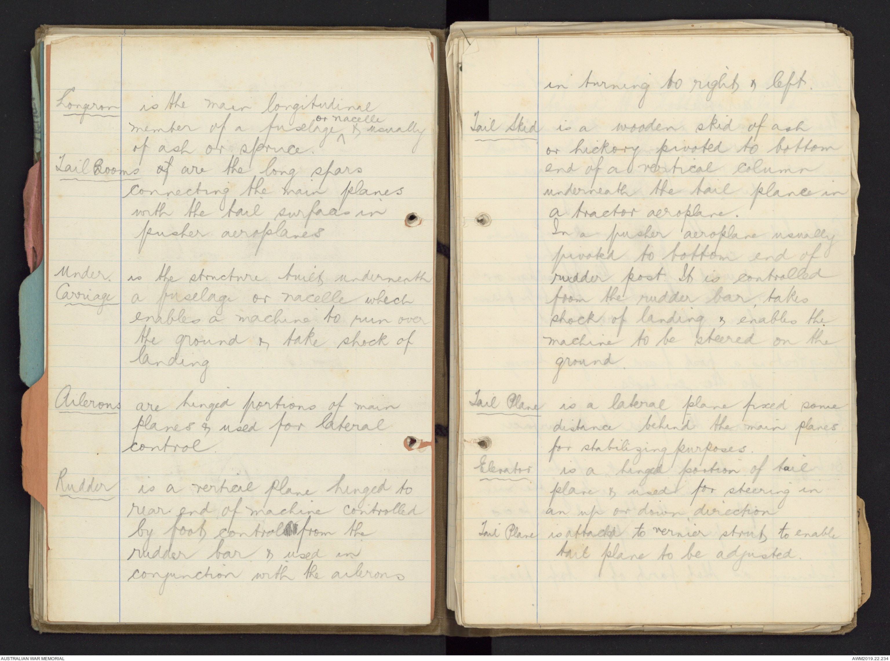
Longeron is the main longitudinal
member of a fuselage ^or nacelle & usually
of ash or spruce.
Tail Booms of are the long spars
connecting the main planes
with the tail surfaces in
pusher aeroplanes
Under Carriage is the structure built underneath
a fuselage or nacelle which
enables a machine to run over
the ground & take shock of
landing
Ailerons are hinged portions of main
planes & used for lateral
control.
Rudder is a vertical plane hinged to
rear end of machine controlled
by foot controlls from the
rudder bar & used in
conjunction with the ailerons
in turning to right & left.
Tail Skid is a wooden skid of ash
or hickory pivoted to bottom
end of a vertical column
underneath the tail plane in
a tractor aeroplane.
In a pusher aeroplane usually
pivoted to bottom end of
rudder post. It is controlled
from the rudder bar, takes
shock of landing & enables the
machine to be steered on the
ground.
Tail Plane is a lateral plane fixed some
distance behind the main planes
for stabilizing purposes.
Elevator is a hinged portion of tail
plane & used for steering in
an up or down direction
Tail Plane is attached to vernier strut to enable
tail plane to be adjusted.
Keel Surface is all sides surfaces of an
aeroplane.
The Fin is an increased keel surface
area set some distance behind
the main planes to increase
directional stability
Centre Section is the framework of struts
& centre plane projecting
upward from the fuselage or
nacelle, to which the tap planes
of a biplane are fixed
King Post is a post fixed to give leverage
to the controls.
Empennage. means the fixed tail surface.
Outrigger is the framework of tail booms
and struts connecting the main
planes with the tail surfaces
in pusher aeroplanes.
The Extension is that part of a top plane
of a biplane projecting
beyond the bottom plane.
Extension Ro Rods support the extension
when machine on ground & act
as flying wires when machine
is in the air.
Rigging, Lecture No.2. 13-7-17.
Span is the distance across the
machine from Wing tip to wing
tip.
Gap is the distance between the
top & bottom plane, usually
measured along the front struts
Gap →
Hand drawn diagram - see original document
Chord is the shortest distance from the
leading edge to the trailing edge.
Hand drawn diagram - see original document
A leading edge
B Trailing "
C Chord
Length is the total projection fore
and aft.
In a tractor length is measured
from extreme end of prop. to
trailing edge of rudder
In a pusher length is
Rigging Lec II 13-7-17
measured from extreme front
of nacelle or strut to other
extremity.
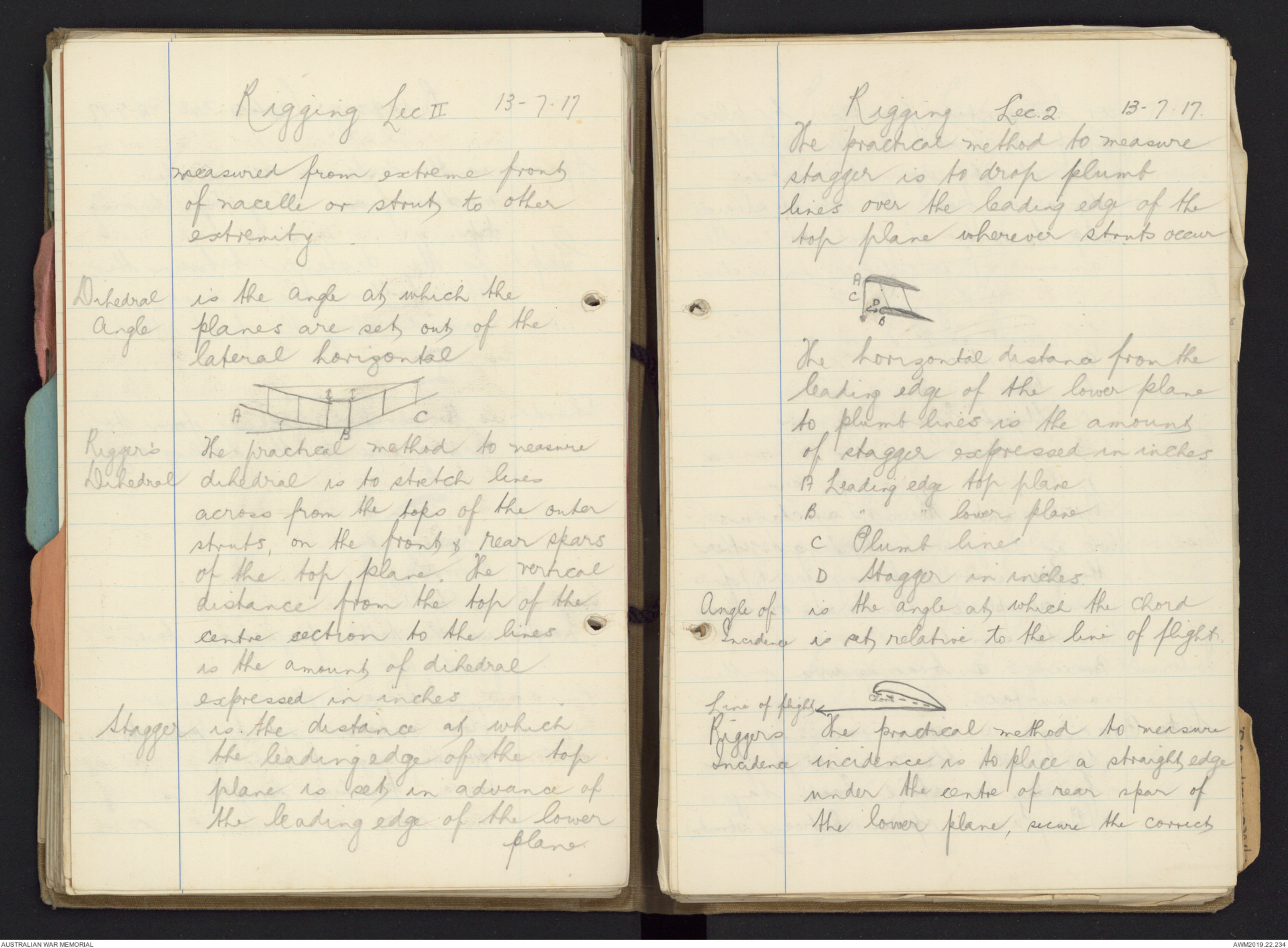
Dihedral Angle is the angle at which the
planes are set out of the
lateral horizonal
Hand drawn diagram - see original document
Rigger's Dihedral The practical method to measure
dihedral is to stretch lines
across from the tops of the outer
struts, on the front & rear spars
of the top plane. The vertical
distance from the top of the
centre section to the lines
is the amount of dihedral
expressed in inches.
Stagger is the distance at which
the leading edge of the top
plane is set in advance of
the leading edge of the lower
plane.
Rigging Lec. 2. 13-7-17
The practical method to measure
stagger is to drop plumb
lines over the leading edge of the
top plane wherever struts occur
Hand drawn diagram - see original document
The horizontal distance from the
leading edge of the lower plane
to plumb lines is the amount
of stagger expressed in inches
A Leading edge top plane
B " " lower plane
C Plumb line
D Stagger in inches.
Angles of Incidence is the angle at which the Chord
is set relative to the line of flight.
Line of flight
Hand drawn diagram - see original document
Riggers Incidence The practical method to measure
incidence is to place a straight edge
under the centre of rear spar of
the lower plane, secure the correct
or horizontal position by placing
a spirit level on the top of
the straight edge. The vertical
distance from the top of straight
edge to centre of front spar is the
amount of incidence in inches.
Hand drawn diagram - see original document
a Front spar
b Rear "
c Straight Edge
d incidence in inches
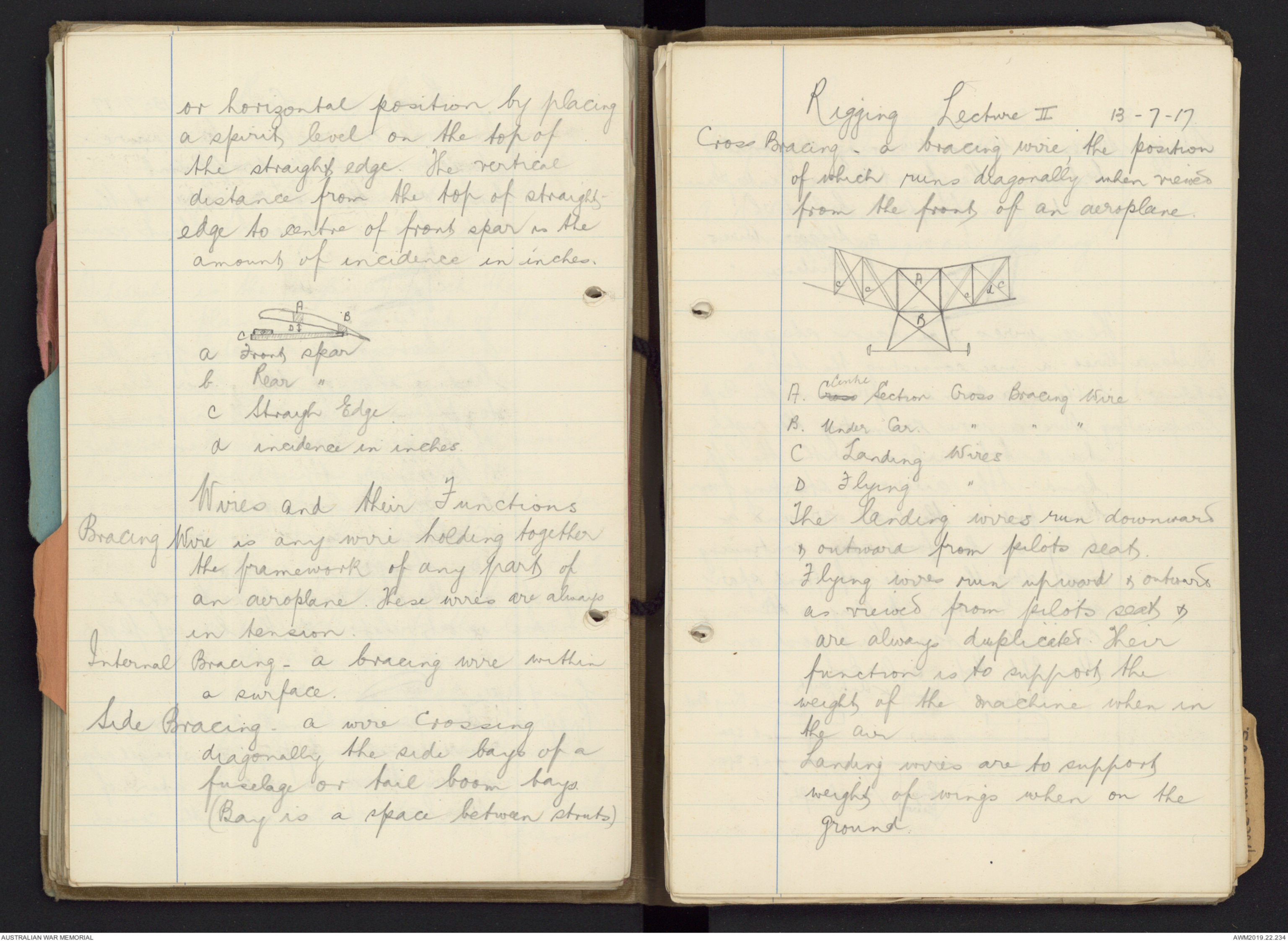
Wires and their Functions
Bracing Wire is any wire holding together
the framework of any part of
an aeroplane. These wires are always
in tension.
Internal Bracing - a bracing wire within
a surface.
Side Bracing - a wire crossing
diagonally the side bays of a
fuselage or tail boom bays.
(Bay is a space between struts)
Rigging Lecture II 13-7-17
Cross Bracing - a bracing wire, the position
of which runs diagonally when viewed
from the front of an aeroplane
Hand drawn diagram - see original document
A. Cross Centre Section Cross Bracing Wire
B. Under Car. " " "
C Landing Wires
D Flying "
The landing wires run downward
& outward from pilots seats.
Flying wires run upward & outward
as viewed from pilots seat &
are always duplicated. Their
function is to support the
weight of the machine when in
the air.
Landing wires are to support
weight of wings when on the
ground.
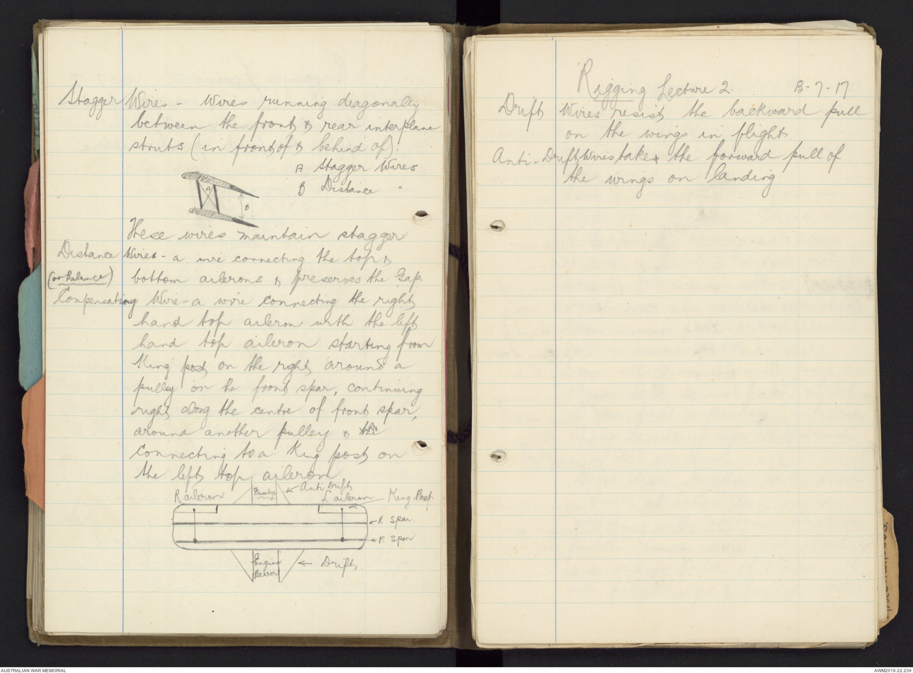
Stagger Wires - Wires running diagonally
between the front & rear interplane
struts (in front of & behind of)
A Stagger Wires
B Distance "
Hand drawn diagram - see original document
These wires maintain stagger
Distance Wires - a wire correcting the tops &
[*(or balance)*] bottom ailerons & preserves the Gap.
Compensating Wire - a wire connecting the right
hand top aileron with the left
hand top aileron starting from
King post on the right around a
pulley on the front spar, continuing
right along the centre of front spar,
around another pulley & the
Connecting to a King post on
the left top aileron
Hand drawn diagram - see original document
Rigging Lecture 2 13-7-17
Drift Wires resist the backward pull
on the wings in flight.
Anti-Drift Wires - takes the forward pull of
the wings on landing
 Deb Parkinson
This transcription item is now locked to you for editing. To release the lock either Save your changes or Cancel.
This lock will be automatically released after 60 minutes of inactivity.