Notebook of James Stuart Leslie Ross - Part 6


the medium of an idler-wheel
Bore is 130 m.m.
Stroke 175 mm
Desax is 18m.m. (left)
Compression 95 lbs per sq in.
Weight of engine incl. Radiator
630 lbs. which
Corresponds to 5.25 lbs per H.P.
The weight laden for a 6 hrs flight
(incl petrol, oil & water) is 1185 lbs.
The Normal R.P.M. 1200.
Maximum R.P.M. 1400.
Full out develops 148 HP.
Petrol Consumption 8 -10 gals per hr.
Oil '' 4 - 4½ pints " "
Both the centrifugal water pump
and Bosch lubricator are fixed
at the rear of engine & driven
direct off the crank shaft at engine
speed.
Order of firing is 1, 5, 3, 6, 2, 4.
11 . 7 .17
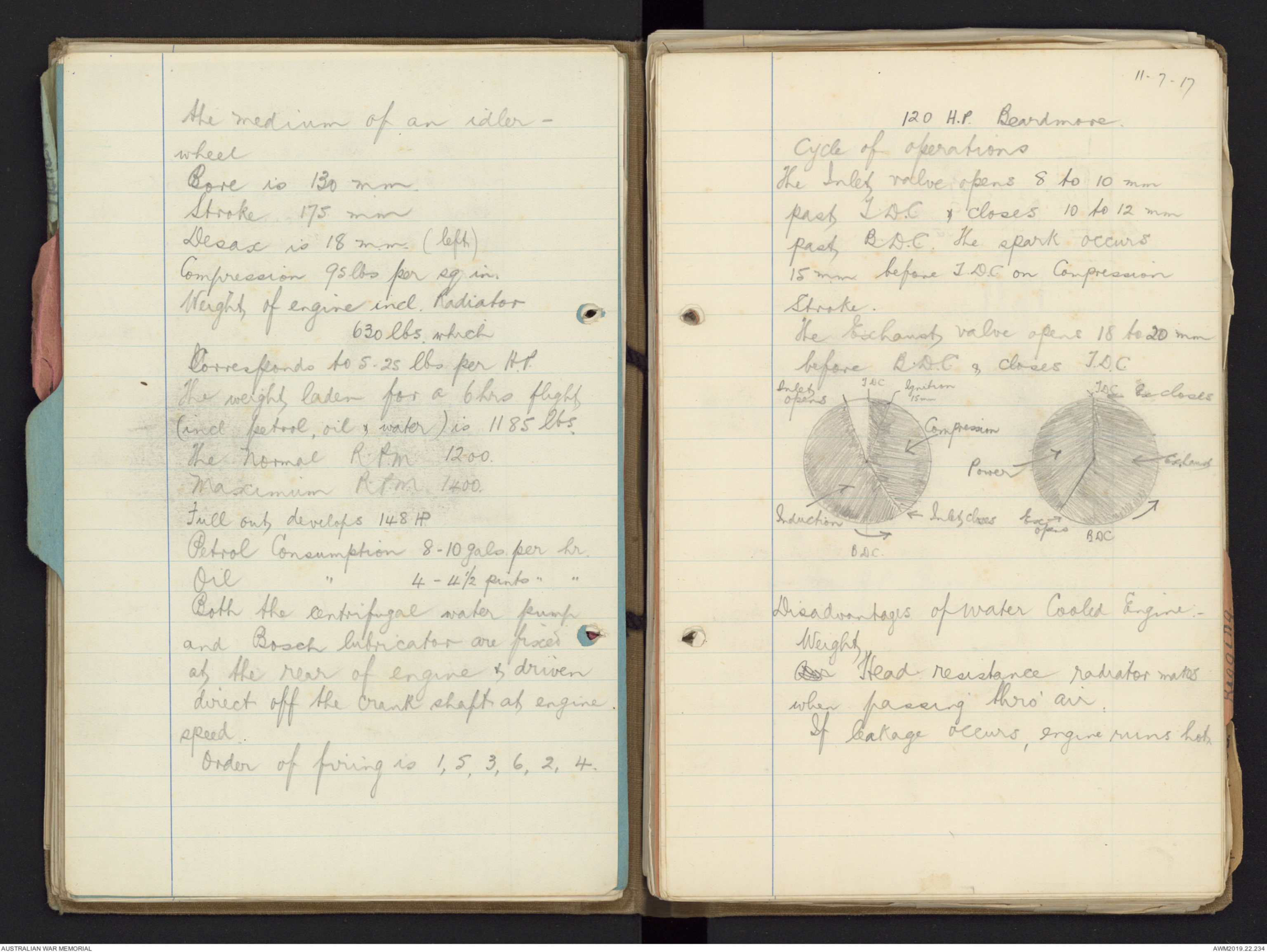
120 H.P. Beardmore.
Cycle of operations
The Inlet valve opens 8 to 10 mm
past T.D.C. & closes 10 to 12 mm
past, B.D.C. The spark occurs
15 mm before T.D.C. on Compression
Stroke.
The Exhaust valve opens 18 to 20 mm
before B.D.C & closes T.D.C.
Hand drawn diagram - see original document
Disadvantages of Water Cooler Engine:-
Weight
Air Head resistance radiator makes
when passing thro' air.
If leakage occurs, engine runs hot.
13 - 7 -17
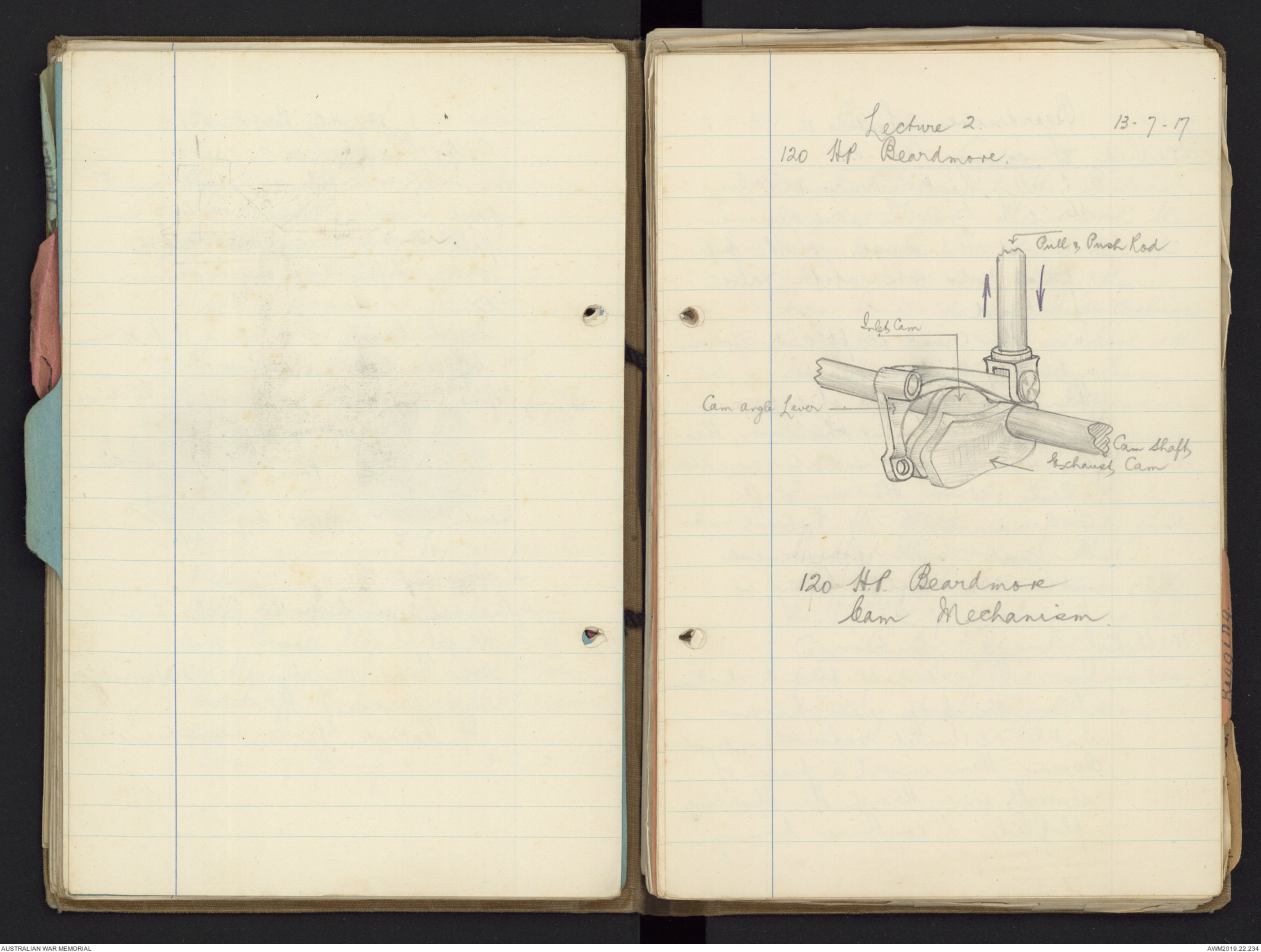
Lecture 2
120 H.P. Beardmore.
Hand drawn diagram - see original document
120 H.P. Beardmore
Cam Mechanism
Beardmore Lecture II. 13-7-17.
Method of Timing Valves
Test all, Rocker Arms & Valve
Stems to have 25/1000 inch clearance
& adjust the length of the pull
& push rods when both valves
are closed
Turn the crank shaft anti-clockwise
until No 1 Piston reaches T. D.C.,
then go to rear end of engine &
take off the timing wheelcover, then
unmesh the intermediate or idler
wheel & turn the cam shaft
clockwise until No1 Exhaust valve
has just closed, then remesh
intermediate wheel & timing is
finished.
Method of Timing Ignition
Turn the crank shaft anti clockwise
from the prop end of engine
until No 1 inlet valve has just
closed, then insert a piece of
straight wire through the sparking
plug hole & continue turning
Beardmore 13 -7-17
Lecture II
crankshaft until the Piston
reached T.D.C., then mark the
wire, measure 15 mm further up
the wire & mark again, then
turn the crank shaft back clockwise
until the 15 mm mark is level with
the sparking plug hole. Then
unmesh magnetos & fully advance
control on right hand magneto
& turn the armature shaft until
the carbon brush until is on No 1 Segment
with the platinum points just
breaking , then remesh that
magneto & Syndrononise right
hand ^magneto with left hand magneto.
Care to be taken that the
plat. points of each magneto are
breaking at exactly the same
moment.
Beardmore Lec 2. 13 -7 -17.
Valve Gear
The valves are operated by a
Single pull & push rod & the
pivoted leaf spring overhead
rocker, at the lower end of the
pull & push rod is fixed a
Cam angle lever which is pivoted
to the Crank case. There are 2
cams on the cam shaft revolving
between & in contact with the
cam angle levers two arms.
The exhaust cam pushes up to
the open exhaust valve & inlet cam
pulls down to open inlet valve.
Both valves lift 7.5 mm
120 HP Beardmore Lecture III 14 - 7 -17
Description & Materials
Cylinders Made of cast iron cast in one
piece with the exhaust valve chamber.
(The inlet valve chamber is detachable )
It is fitted by means of a ground
joint & a brass locking ring).
The cylinders are fitted with steel bases
which are screwed & sweated on.
Water Jackets Made of copper, deposited by
electrolysis,
Pistons. Made of steel machined from the
solid They have concave heads hand drawn diagram - see original
(Explosion more concentrated owing to concavity).
Fitted with 3 cast iron Piston rings which
have stepped joints hand drawn diagram - see original fitted at 120°.
Connecting Rods made of 'H" Section chrome nickel Steel.
Big End is made in 2 pieces & is held
together by 4 bolts & is lined with white Metal.
As small scoop is formed on the bottom
of big end for lubrication purposes
The small end is lined with phospor
Beardmore
bronze.
Gudgeon Pin. holds connecting rod into piston.
Made of C.N. Steel, case-hardened,
hollow ( for lightness ) & for lubrication of
small end bearing). It is hel fitted
into piston by 2 tapers, key & keyway,
& a grub screw.
Valves. made of Tungsten steel (used because
it will stand great heat). Both valves are
same size. Inlet is Mushroom shaped &
Exhaust Valve is cone-shaped.
Crank Shaft: made of C. N Steel in 3 Parts
Parts:- (1) Main Shaft (2) Propellor Sleeve
(3) Driving Shaft
The prop sleeve is fixed to main shaft by
being a tapered fit, by key & keyway, &
a locking nut. Locking nut is secured
by small grub screws.
Driving Shaft. Consists of the driving gear wheels &
is fitted on rear end of crank shaft.
It is held by 2 keys & by being a
pressed fit
hand drawn diagram - see original
120.HP Beardmore Lecture III 14 - 7- 17.
Crank Shaft has 6 Throws set up in pairs at
120°. Pairs Nos 1 & 6, 2 & 5, 3 & 4 .
Crank Shaft revolves in 8 bearings - 7
white metal ones & 1 radial ball-bearing
which is fitted in the thrust box.
Crank Shaft is hollow being bored out
with a taper hole which is smallest at
prop end.
How to take Cam Shaft out of Engine
Take off Spur wheel at prop end of
cam shaft, then release all pull &
push rods & cam angle levers from
crank case & remove the two set screws on
side of crank case & take off timing
wheel cover & undo the three locking
nuts of the rear end bearing & cam shaft
can then be drawn out from the
rear
120 HP. Beardmore Lecture 4. 16.7.17
Cam Shaft. Chrome Nickel steel. Cams case -
hardened & machined from the solid & is
carried in 4 phosphor bronze bearings
Water Circulation. The water is circulated by a
centrifugal pump which is fixed at
rear ^end of engine & driven direct off the
crankshaft at engine speed
Circulation. Water flows by gravity from the
bottom of radiator thro' a U shaped
copper pipe to the centre of water pump.
It is forced out of the side of the pump
& passes thro' a copper pipe to bottom
of cylinders, circulates all round the
cyls. & passes out at the top near Exhaust
valve into a return water pipe back
to top of radiator. Two bye-passes
lead from the return water pipes to
the carburetters, passes round the jackets
& returns thro' a small pipe to the
U shaped copper pipe. Water capacity
is 6 gallons
(Hot Water round carburetter vaporises
mixture more quickly).
Advantages of Beardmore ^ Even cooling, economical oil Engine can be run
for a long time, being water cooled
Disadvantages extra weight. If water becomes
clogged, engine will run hot.
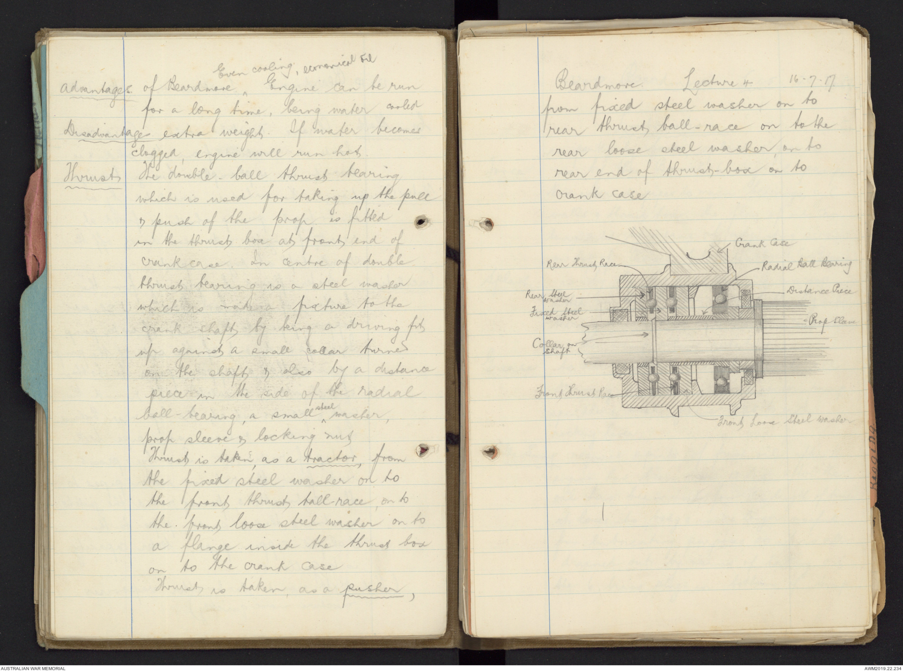
Thrust The double-ball thrust bearing
which is used for taking up the pull
& push of the prop is fitted
in the thrust box at front end of
crank case. In centre of double
thrust bearing is a steel washer
which is made a fixture to the
crank shaft by being a driving fits
up against a small collar turned
on the shaft & also by a distance
piece in the side of the radial
ball-bearing, a small ^steel washer,
prop sleeve & locking nut
Thrust is taken, as a tractor, from
the fixed steel washer on to
the front thrust ball-race, on to
the front loose steel washer on to
a flange inside the thrust box
on to the crank case
Thrust is taken, as a pusher,
Beardmore Lecture 4 16.7.17
from fixed steel washer on to
rear thrust, ball-race on to the
rear loose steel washer, on to
rear end of thrush-box on to
crank case
Hand drawn diagram - see original document.
120 HP Beardmore Lec 5. 20-7-17
Lubrication.
is partly by force, splash & grease.
Force is by the Bosch 6-way oil pump,
thro' external pipes to main bearings, cyl.
walls & thrust box. The flow of oil can
be regulated by means of adjusting screws
on top of Bosch lubricator (Bigend Cam, Gudgeon).
Splash is by the big ends having a scoop
fitted on the bottom half of the big end
bearing which dips into its own compartment
in the sump when rotating.
Grease to all external working parts, all
driving wheels including water-pump
spindle & small grease caps to each
rocking lever.
The Sump requires 4 pints of fresh oil after the
engine has been run 12 hrs. After the
oil has been used for this length of time
it loses its body & is no longer useful
for the lubricating purposes, so it is all
drained out by means of taking out
the 6 brass plugs in bottom of Sump
Crank Case is then thoroughly cleaned out
with paraffine & fresh oil is put in
from half a pint to ¾ of a pint being
placed in end compartment. The oil
can be poured either thro' the
breathers or by raising the cam
angle lever covers.
Breathers relieve Compression in Crank Case,
assists in Cooling & allows vaporised
oil to escape.
Bosch Lubricator
The pump case is kept filled with
oil by gravity, from the oil tank.
The pump spindle is driven at
engine speed but is internally geared
down to 1/25 Engine Speed by means of a
worm & sector gearing. Two Cams are
mounted on a spindle the upper &
larger Cam actuating 6 pump aplungers
The lower & smaller one actuating 6
valve plungers thus giving 6
deliveries of oil
The 4 Strokes of Pump.
1. The valve plunger is raised by a
Beardmore Lec 5.
cam.
2. The pump plunger is raised drawing
oil into the pump valve through ports
by a hole in the valve plunger
3. The valve plunger is depressed
cutting off the supply of oil &
simultaneously by means of a flat on
the side of the valve plunger opens
the way from pump plunger to delivery
pipe.
4 Pump plunger is depressed forcing oil
out of pump valve via the flat to
the delivery pipe.
No 1 Delivery pipe goes to No 1 Main
Bearing & Thrust bearing
No 2 Delivery pipe goes to 1, 2, & 3 cyl.
walls.
No 3 Delivery pipe goes to 4, 5 & 6 cyl. walls
No 4 Delivery pipe goes to 6 & 7 main
bearings.
No 5 Delivery pipe goes to 2 & 3 main bearings
No 6 Delivery Pipe " " 4 & 5 " "
The adjustment of the oil pump
supply - 3½ pints per hr.
Screw all the adjusting screws down in
a clockwise direction as far as
possible then screw back. Nos 1,4,5 & 6,
2½ turns & lock. Nos 2 & 3 1 turn & lock
The oil used both in Summer &
Winter is Vacuum B. B. The oil pump
gives 48 pulsations of oil per minute
at 1200 R.P.M of engine
Pump plungers are numbered
anti-clockwise from space.
120.HP. Beardmore Lec 6. 23-7-17.
Gearing & Magnetos.
Two running magnetos are fitted at
prop end of engine & are driven direct
off cam shaft. The mag. armature
revolves 3 times to camshafts one
& the crankshaft two. Type of mag.
used is the Bosch D.V.6 which give
2 sparks per rev of their armatures, each
mag. supplying the 6 cyls. There is also
a C.A.V. self starting magneto fitted
near the pilot's seat & is used for
starting-up purposes only
Wiring of the C.A.V. self starting Magneto.
Connect with High Tension wire the
large terminal ^on the C A V to the central
terminal on right hand magneto
& connect small terminal on C a V
to the switch & from the switch
to earth
How to Start Engine
See that all switches are off,
turn petrol on, with throttle a
 Marisa Bortolotto
This transcription item is now locked to you for editing. To release the lock either Save your changes or Cancel.
This lock will be automatically released after 60 minutes of inactivity.