Notebook of James Stuart Leslie Ross - Part 5


halves secured by a bolt
passing between each cylinder
A Groove is cut on the portions
which clamps the cyls, into
which fits a collar turned
on the cyl thus preventing
the cyls. being blown off,
cylinders being prevented from
turning by a small key, between
cylinder & crank cases
Support of Crank Case Crank Case is support by being
bolted at the back to the
thrust, box & at the front to
the gear box which in turn
are supported on the shaft by
ball-bearings
110-HP Clergèt Lec 4 17-7 17
Cylinders C.N. Steel, turned from a forging.
Thickness of Cyl walls 3mm. A collar
is turned on the skert which fits into a
recess turned in the crank case, this
preventing cyl. from being offblown.
They are prevented from turning by a small
key fitting between crank case & cylinder.
Fins are turned for cooling & strengthening
purposes, two holes are drilled in the head
to accomodate the valves, the seatings of
these being screwed into cyl. Two brackets
are also screwed in to carry the rocker arms
which operate the valves. Provision is
provided for two sparking plugs, one at
leading edge & one at rear (later engine both
plugs in front). Cyls. must be kept bright and
clean to enable internal defects to be
discovered from outside. (Blue streaks
denote broken obturator rings).
Trust Box is situated on rear of engine, rotates
on long end of shaft & is supported by
2 ball bearings, one being radial & one
self-aligning. It carries the spur wheel which is
used to drive the auxiliaries namely, the oil
pump, air pump & magnetos, & also the
distributor ring which is used to
collect currents from a stationary carbon
brush & convey it by means of a
wire to the plug. Between the
two ball bearings is fitted a double acting
thrust race which is designed to take
thrust, both in tractor & pusher directions.
Tractor Thrust is first taken on a solid collar
turned in the thrust box, through
the outer ball race, then on to the outer
ball cage, then to central ball race
on to the distance piece & thro'
the self-aligning ball-bearing to the
crank web.
Pusher Thrust is first taken on a screwed collar
screwed into the thrust box, thro' the
inner ball-race to the inner ball cage
then to centre ball race, distance piece,
radial ball bearing & is finally taken
by a locking nut screwed on the shaft
110 H.P. Clergèts Lecture V. 21.7.17
Valve Gearing & Timing
Valves are mechanically operated by a system
of gears contained in a gear box
which rotates on small end of shaft
In the centre of gear box is placed
a ball bearing which supports it
on the shaft. 18 holes are drilled
around the gear box these being
brushed with phosphor bronze forms
the guides for the tappets.
Keyed into the gear box are 2
internally toothed rings which are
used to drive the inlet & exhaust
cam gears, these having 18 teeth
& run concentric to the crank
shaft. One the eccentric shaft
is place 2 externally toothed
wheels which have 16 teeth & run
eccentric to the crank shaft therefore
only meshing with the gear ring
at one point on each fourth
tooth of the gear wheel is an
extension or cam & this wheel gains
2 teeth for every rev. of engine
On one rev, an extension comes
into contact with a tappet & pushes
open the valve but on the next
rev. the wheel having gained 2
teeth the tappet drops into the
recess behind & the valve is not
opened. On the 3rd rev. 2 more
teeth having been gained
the next extension comes in
alignment, & the valve is opened.
By this method each valve is
opened every 2 revs.
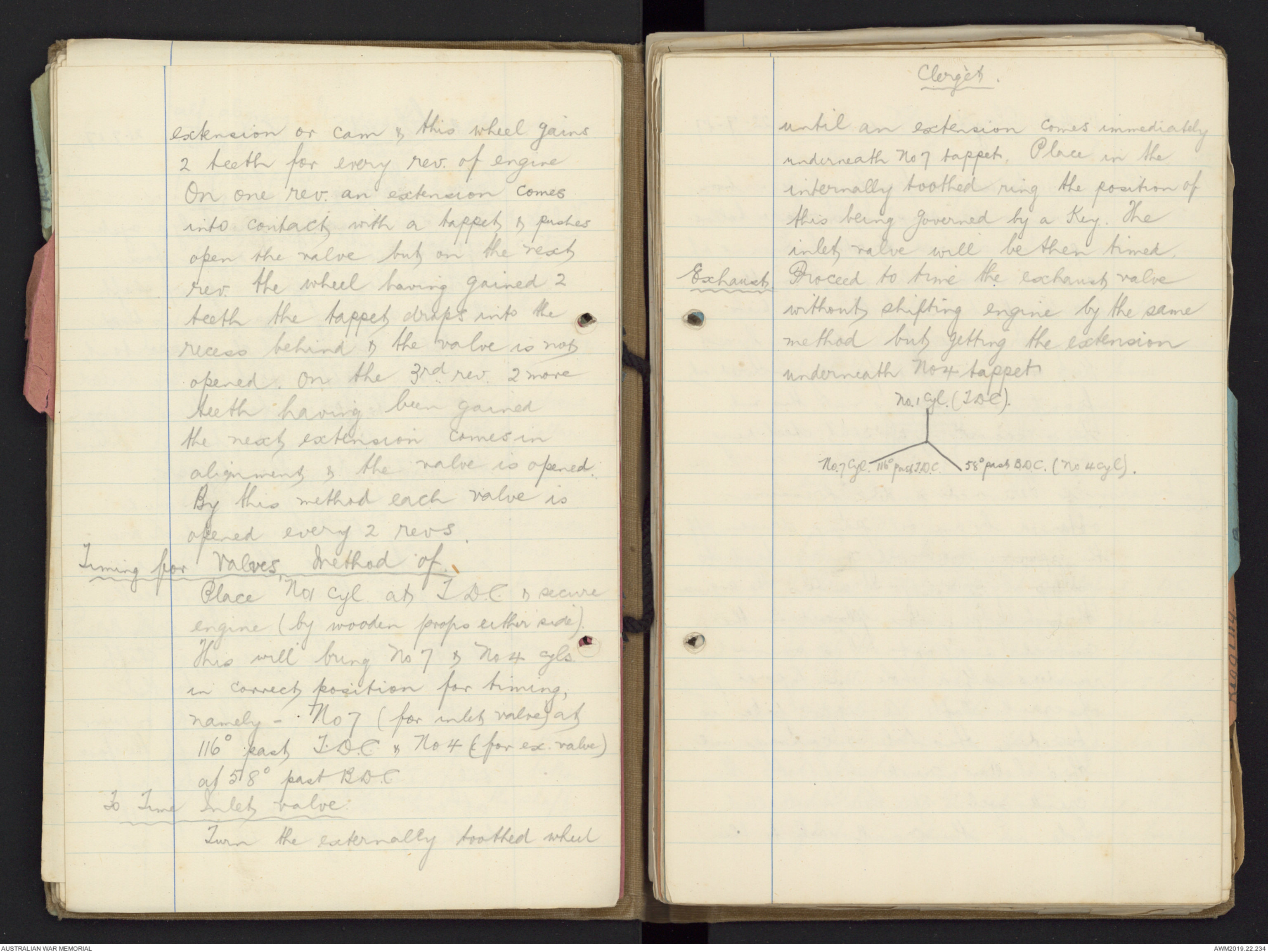
Timing for Valves Method of.
Place No 1 Cyl at T.D.C. & secure
engine (by wooden props either side).
This will bring No 7 & No 4 cyls.
in correct position for timing,
namely - No 7 (for intel valve) at
116o past T.D.C. & No 4 (for ex. valve)
at 58o past B.D.C.
To Tune Intel Valve.
Turn the externally toothed wheel
Clergèt.
until an extension comes immediately
underneath No 7 tappet. Place in the
internally toothed ring the position of
this being governed by a key. The
inlet valve will be then timed.
Exhaust Proceed to time the exhaust valve
without shifting engine by the same
method but getting the extension
underneath No 4 tappet
Diagram - see original document
110 HP Clergèt Lecture 6. 22-7-17
Nose Piece is bolted front of gear box
& carries the prop. It is made hollow
& prop is secured to it by means of
a steel base sliding up on the
tapered portion of the nose piece,
being prevented from turning by a
key & keyway & firmly secured at
front by a locking nut, this nut
being secured by a split steel ring.
Lubrication is delivered under pressure
obtained by an oil pump driven off
the spur-wheel, oil coming back to
pump by gravity. It enters the engine
through a union placed on the
central support. This union
registers with a hole in tapered part
of crank shaft. A copper pipe is
fixed in this hole & conveys oil
thro' hollow crank shaft to the
crank web, up thro' a drilled
hole in the crank web to the
Clergèts
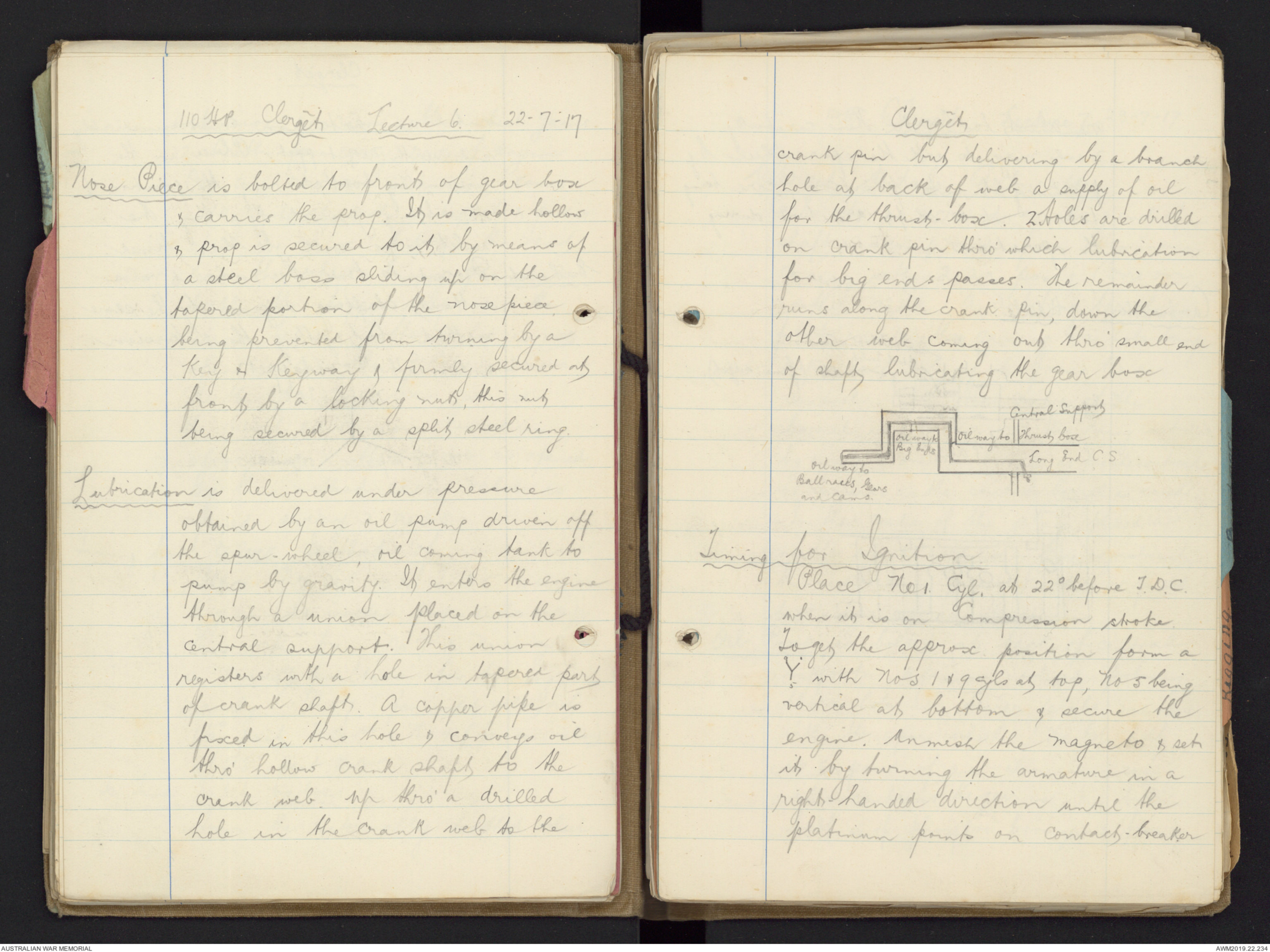
crank pin but delivering by a branch
hole at back of web a supply of oil
for the thrust-box. 2 holes are drilled
on crank pin thro' which lubrication
for big ends passes. The remainder
runs along the crank pin, down the
other web casing out thro' small end
of shaft lubricating the gear box
Diagram - see original document
Timing for Ignition
Place No 1. Cyl. at 22o T.D.C.
when it is on Compression stroke.
To get the approx position form a
Y with Nos 1 & 9 cyls at tap, No 5 being
vertical at bottom & secure the
engine. Unmesh the magneto & set
it by turning the armature in a
right handed direction until the
platinum points on contact-breaker.
are about to break. Then carefully
mesh magneto with the spur wheel by
placing it into position, care being
taken not to shift armature during
the operation.
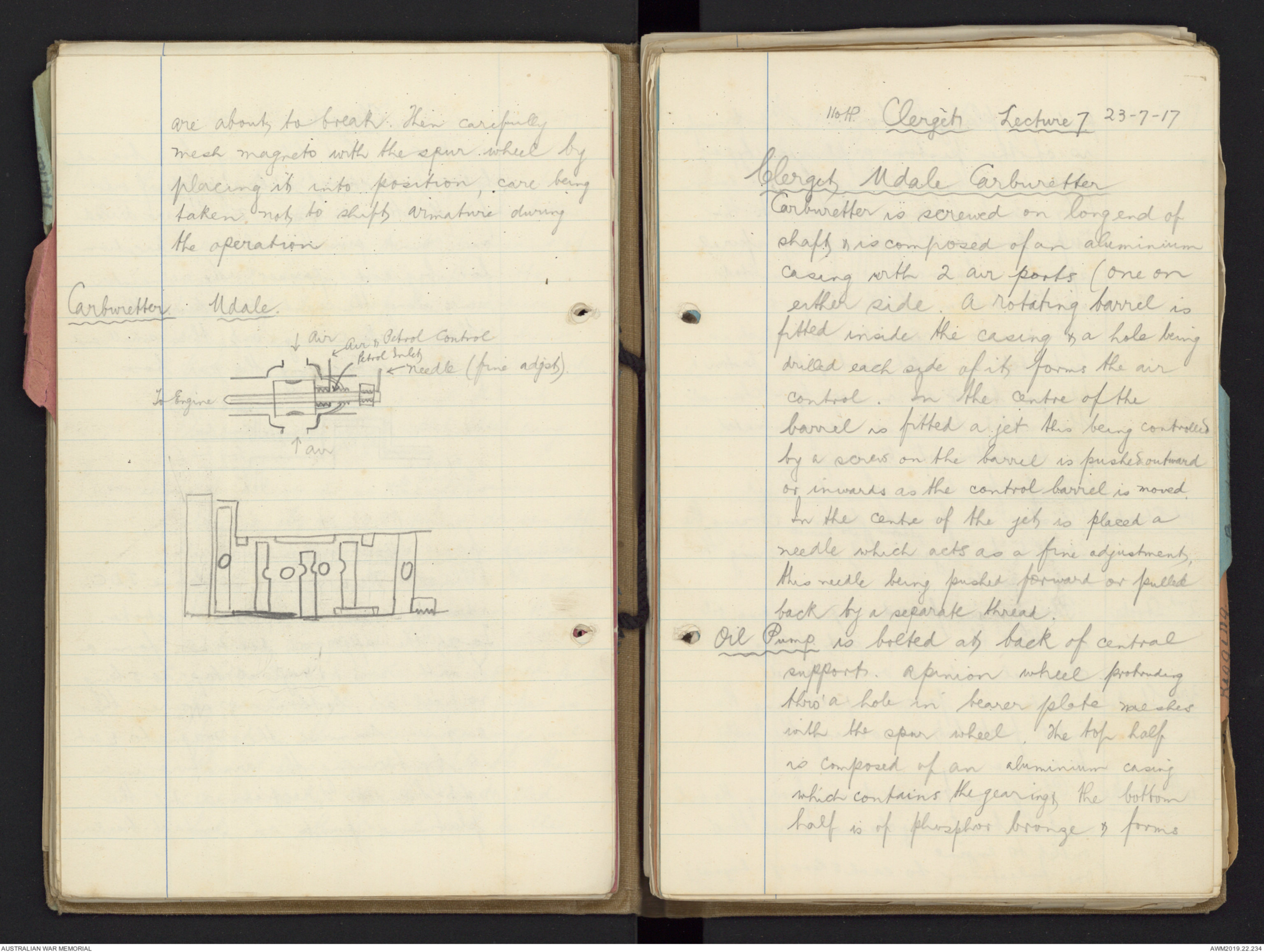
Carburetter. Udale.
Diagram - see original document
110.HP. Clergèts Lecture 7 23-7-17
Clergèt Udale Carburetter
Carburetter is screwed on long end of
shaft & is composed of an aluminium
casing with 2 air ports (one on
either side. A rotating barrel is
fitted inside the casing & a hole being
drilled each side of it forms the air
control. In the centre of the
barrel is fitted a jet this being controlled
by a screw on the barrel is pushed outward
or inwards as the control barrel is moved.
In the centre of the jet is placed a
needle which acts as a fine adjustment,
this needle being pushed forward or pulled
back by a separate thread.
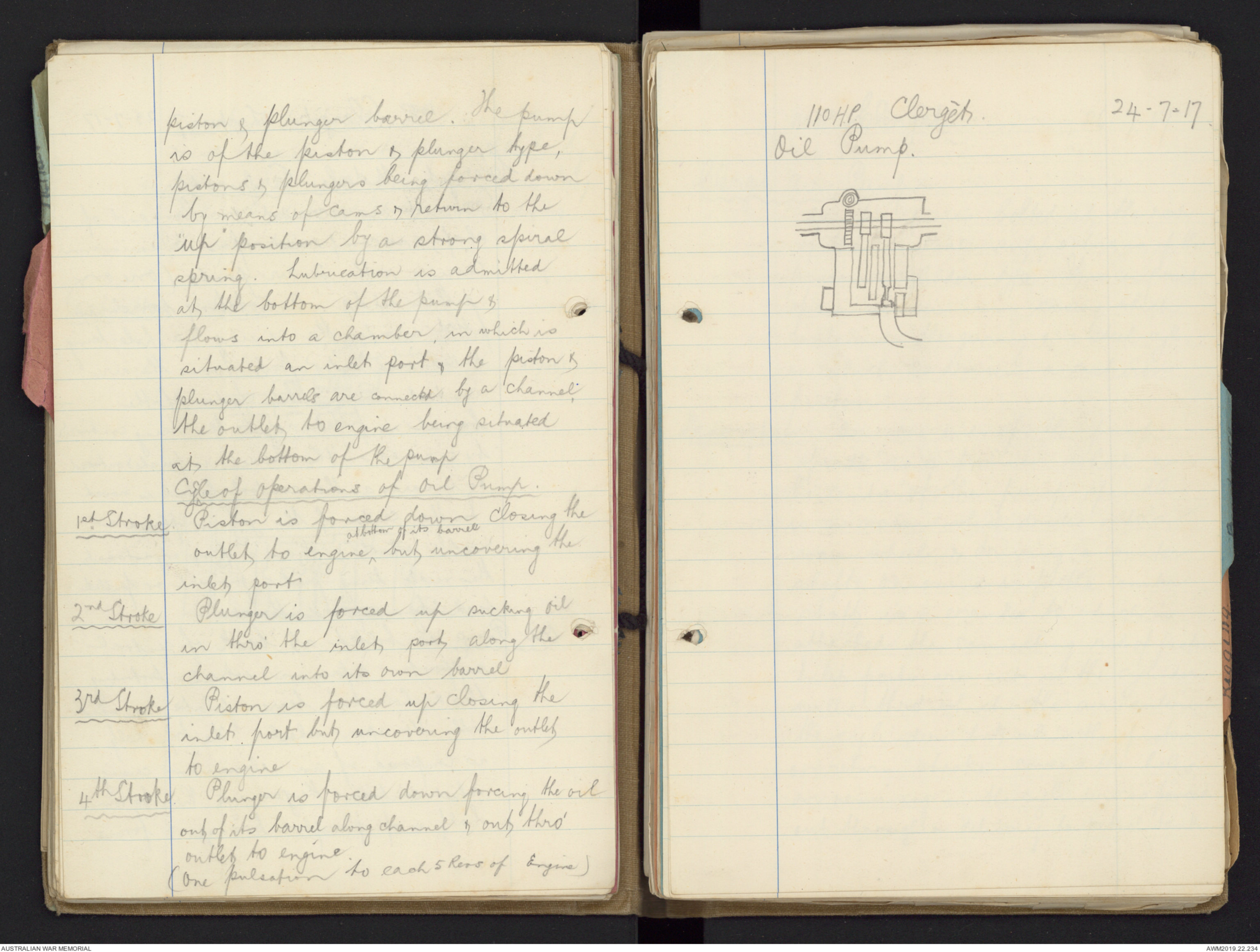
Oil Pump is bolted at back of central
support. A pinion wheel protruding
thro' a hole in bearer plate meshes
with the open wheel. The top half
is composed of an aluminium casing
which contains the gearing &, the bottom
half is of phosphor bronze & forms
piston & plunger barrel. The pump
is of the piston & plunger type,
pistons & plungers being forced down
by means of cams & return to the
"up" position by a strong spiral
spring. Lubrication is admitted
at the bottom of the pump &
flows into a chamber, in which is
situated an inlet port, the piston &
plunger barrels are connected by a channel,
the outlet to engine being situated
at the bottom of the pump
Cycle of Operations of Oil Pump.
1st Stroke Piston is forced down closing the
outlet to engine, ^at bottom of its barrel but uncovering the
inlet port.
2nd Stroke Plunger is forced up sucking oil
in thro' the inlet port along the
channel into its own barrel
3rd Stroke Piston is forced up closing the
inlet port but uncovering the outlet
to engine
4th Stroke Plunger is forced down forcing the oil
out of his barrel along channel & out thro'
outlet to engine.
(One pulsation to each 5 Revs of Engine)
110 H.P. Clergèts. 24-7-17
Oil Pump.
Diagram - see original document
110 HP. Clergèts 26.7.17
Clergèt Air Pump
Air pump is bolted at the rear
of the central supports & is of the
piston & cylinder type. It is composed
of an aluminium casing which
contains the gearing & a steel cyl.
in which is driven a cast iron
piston.
Description On one end of the pump
spindle is a pinion wheel & in
the centre of the pump spindle
is a worm which drives onto a
worm wheel & driving a counter
shaft. On one end of the counter
shaft is a crank to which is
attached the connecting rod of piston.
Inlet ports are cut in the cylinder
walls thro' which the air enters
the cylinder but when the piston
or return stroke covers the holes,
air remaining in the cylinder is forced
out through a delivery to petrol tank.
A non-return valve is fitted to the
outlet which is a ball & spring valve
this preventing any ^back pressure from
escaping thro' the cyl. A safety valve
is fitted to ensure an even pressure
in the tank, which is about 4lbs
to sq. inch. This is also worked by
a ball & spring valve.
Pulsator Glass.
no of revs. engine is doing may
be counted by observing no. of
pulsations. On. Mono. -
multiply pulsations per min x 100 & divide
by 9 (cyls.).
Pulsator Glass is fitted to
dashboard & dri ensures that
oil pump is working.
Questions on Clergèts 26.7.17
How many ball-bearings on shaft?
6 in all - 2 in Thrust box 2 in
gear box & 2 on crank pin.
Thrust & gear are Main bearings.
What are frequent causes of
engine failure?
Faulty Ignition or Lubrication (f
Magnetos. 27.7.17
Magnets are made of Tungsten Steel &
are U shaped (Tungsten retains
magnetism for long time).
Armature built up of soft iron plates
(Swedish iron) insulated by mica or shellac.
Must be at least 50 times No. of turns in
Secondary as in Primary.
Correct distance for break between
plat points .4mm. Plat is used
as it wont rust.
Keep mag. clean, oil sparingly &
avoid getting it wet.
Safety Spark Gap 4 to 5 mm.
Lecture I 11-7-17
120 H.P. Beardmore.
Description - 6 cyl. Vertical
Water Cooled (Even cooling lowers oil consump., & vaporises
mixture in carb).
Cylinders desaxed or offset &
each separately with the head of
cylinder & exhaust valve chamber
in one piece.
Cylinders numbered from prop. end.
Two overhead valves operated by a pull
and push rod pulling down to
open the inlet, pushing up to open
the exhaust. Double ignition &
the C.A V. self-starting magneto.
Two magnetos & each supplies 6 cyls.
Two plugs in each cyl ignite at
exactly same time.
Two carburetters each supplying 3 fronts
& 3 rear cylinders respectively. This
engine can be used either in a
pusher or tractor machine owing
to the design of thrust box.
Both the Cam shaft & Crank
shaft revolve anti-clockwise thro'
 Marisa Bortolotto
This transcription item is now locked to you for editing. To release the lock either Save your changes or Cancel.
This lock will be automatically released after 60 minutes of inactivity.