Notebook of James Stuart Leslie Ross - Part 4
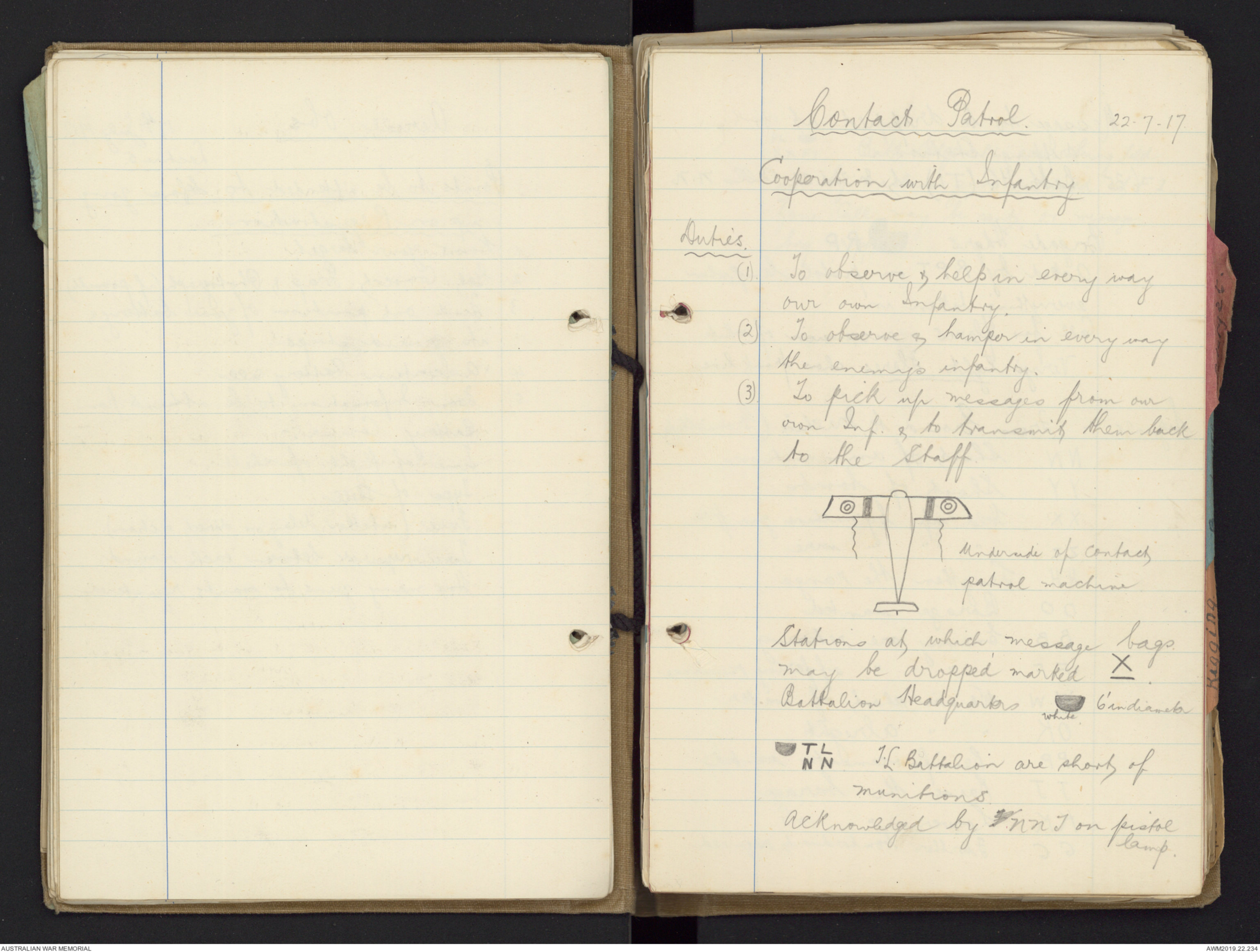


Contact Patrol. 22.7.17.
Cooperation with Infantry.
Duties.
(I) To observe & help in every way
our own Infantry.
(2) To observe & hamper in every way
the enemy's infantry.
(3) To pick up messages from our
own Inf. & to transmit them back
to the Staff
Hand drawn diagram - see original document
Stations at which message bags.
May be dropped marked X.
Battalion Headquarters Drawing - see original document
Drawing - see original document
T.L. Battalion are short of
munitions.
Acknowledged by F NNT on pistol
lamp.
Message to be dropped at
dropping station.
6.35 Batt HQ (TL) at In 36 d 35 calls N.N.
Brigade Hdqrs Drawing - see original document
Acked by RPT on pistol lamp, when
everything taken in.
Call for flares - succession of white
Very's lights. Flares show front line.
Signals :- From Ground to Machine (Ground Strips)
NN Short of ammunition
YY Short of bombs
XX Held up by machine gun fire
ZZ " " " wire
HH Lengthen the range
OO Barrage wanted.
BB Enemy are retiring
FF " " offering resistance
WW We are short of water
OK " " alright.
PP Reinforcements wanted.
JJ Raise the barage.
KK Lower " "
GG Further bombardment required.
PL Hand drawn diagram - see original document
XXFI. Batt Hdqrs PL are being held
up by machine gun situated at F1.
Zone Call may be sent, or message
bag dropped.
Types of Reconnaissance 24.7.17
1. Long Reconnaissance
2 Short Reconn
3 Flash "
4 Photographic "
5 Trench "
6 Night "
7 Special "
8 Line "
Long Information required on Long Reconn.
Trains, transports, trenches, trees
(woods) T's.
Trains, Time place, & nature of rolling
stock.
Trenches, new, well behind lines.
Short Same as long.
Flash go out at dusk to watch for gun
flashes. always done by Corps Sqdn
Photo. Formations of 2 or 3 machines
Trench Contact Patrol Flight
Night what railways & Roads being used &
what villages occupied. Also do bombing.
Special Anything new.
Line Reconn. from point to point.
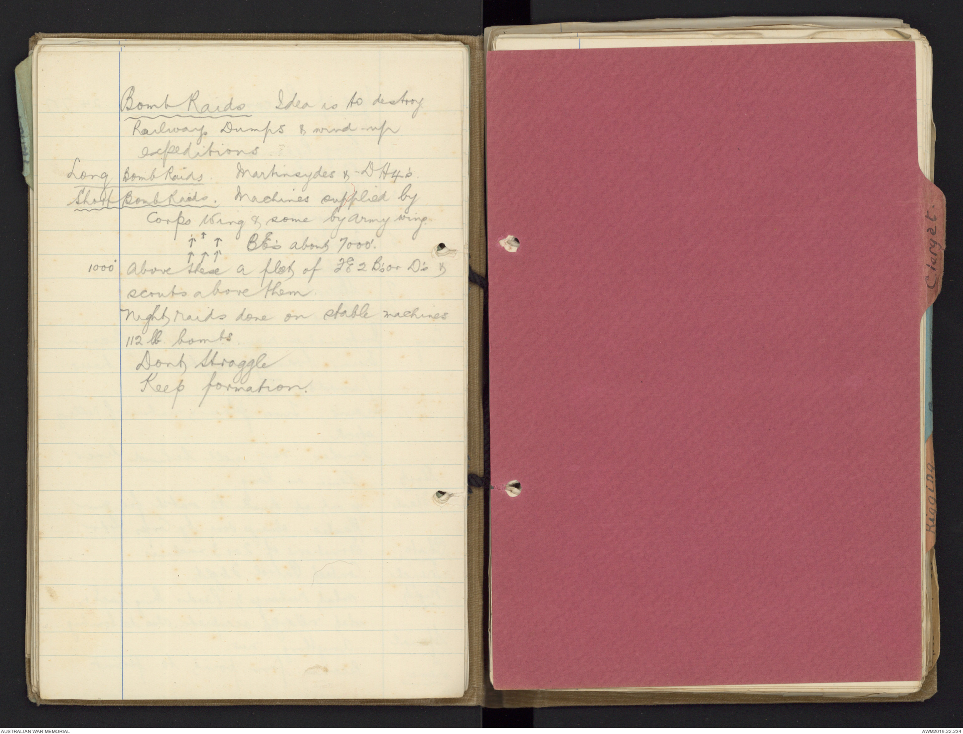
Bomb Raids Idea is to destroy
Railways, Dumps & wind up
expeditions
Long Bomb Raids. Martinsydes & DH4's.
Short Bomb Raids. Machines supplied by
Corps Wing & some by Army wing.
Diagram - see original document
1000' above these a plot of F E 2 B's or D's &
scouts above them.
Night raids done on stable machines
112 lb bombs.
Dont Straggle
Keep formation.
Engines. 11.7.17
The Internal Combustion Engine
is worked under the otto Cycle
or 4 Stroke principle which makes
it necessary to employ three strokes
to prepare the engine for 1 actual
stroke of power, the names of
strokes being;-
No 1 Induction
" 2 Compression
" 3 Power
" 4 Exhaust.
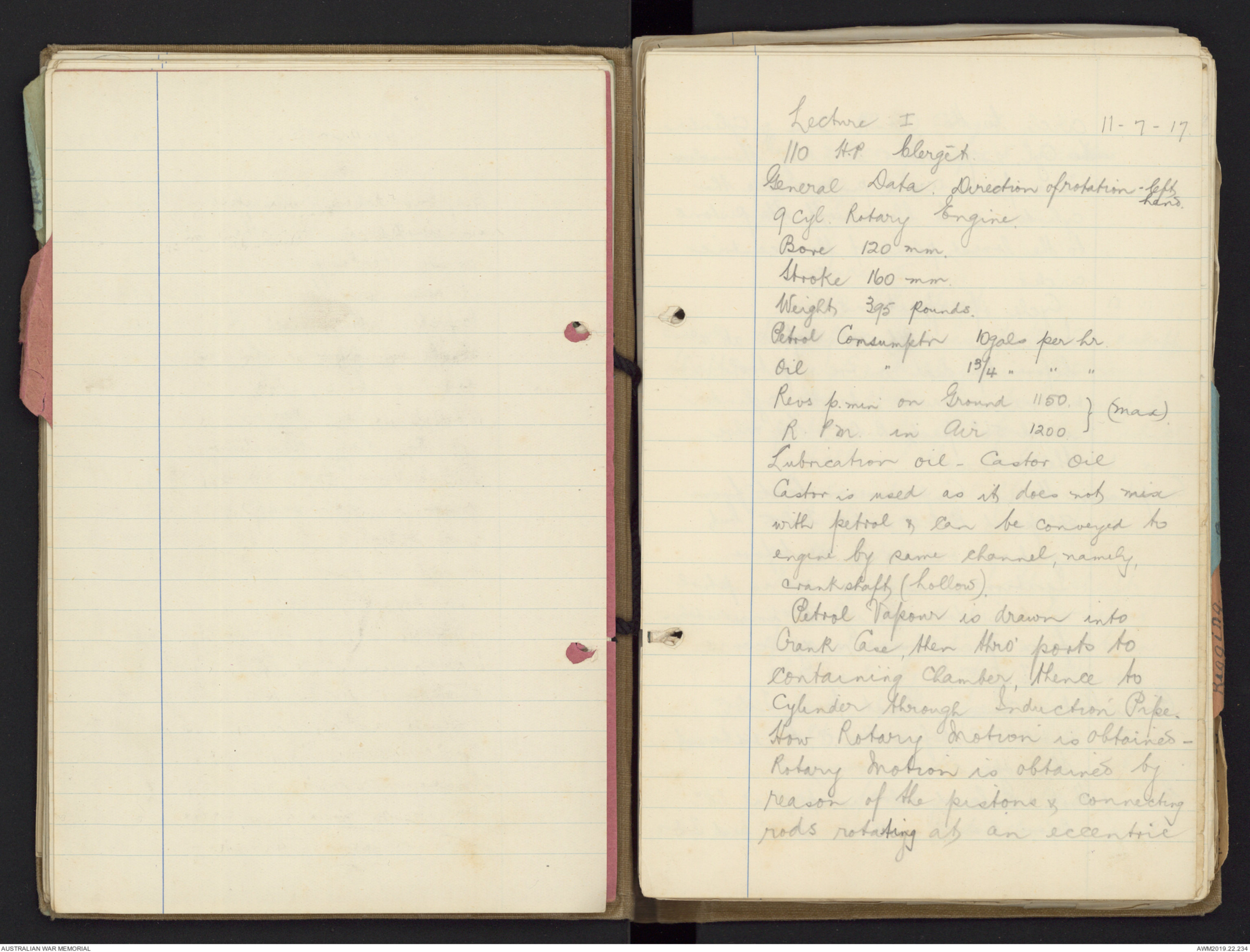
Lecture I 11-7-17
110 H.P. Clergèt.
General Data. Direction of rotation - left
hand.
9 cyl Rotary Engine.
Bore 120 mm.
Stroke 160 mm.
Weight 395 pounds.
Petrol Consumption 10gals per hr.
Oil " 1¾ " " "
Revs p.min on Ground 1150. }(Max).
R.PM. in Air 1200. }
Lubrication oil - Castor Oil
Castor is used as it does not mix
with petrol & can be conveyed to
engine by same channel, namely,
crankshaft (hollow).
Petrol Vapour is drawn into
Crank Case, then thro' ports to
Containing Chamber, thence to
Cylinder through Induction Pipe.
How Rotary Motion is obtained -
Rotary Motion is obtained by
reason of the pistons & connecting
rods rotating at an eccentric
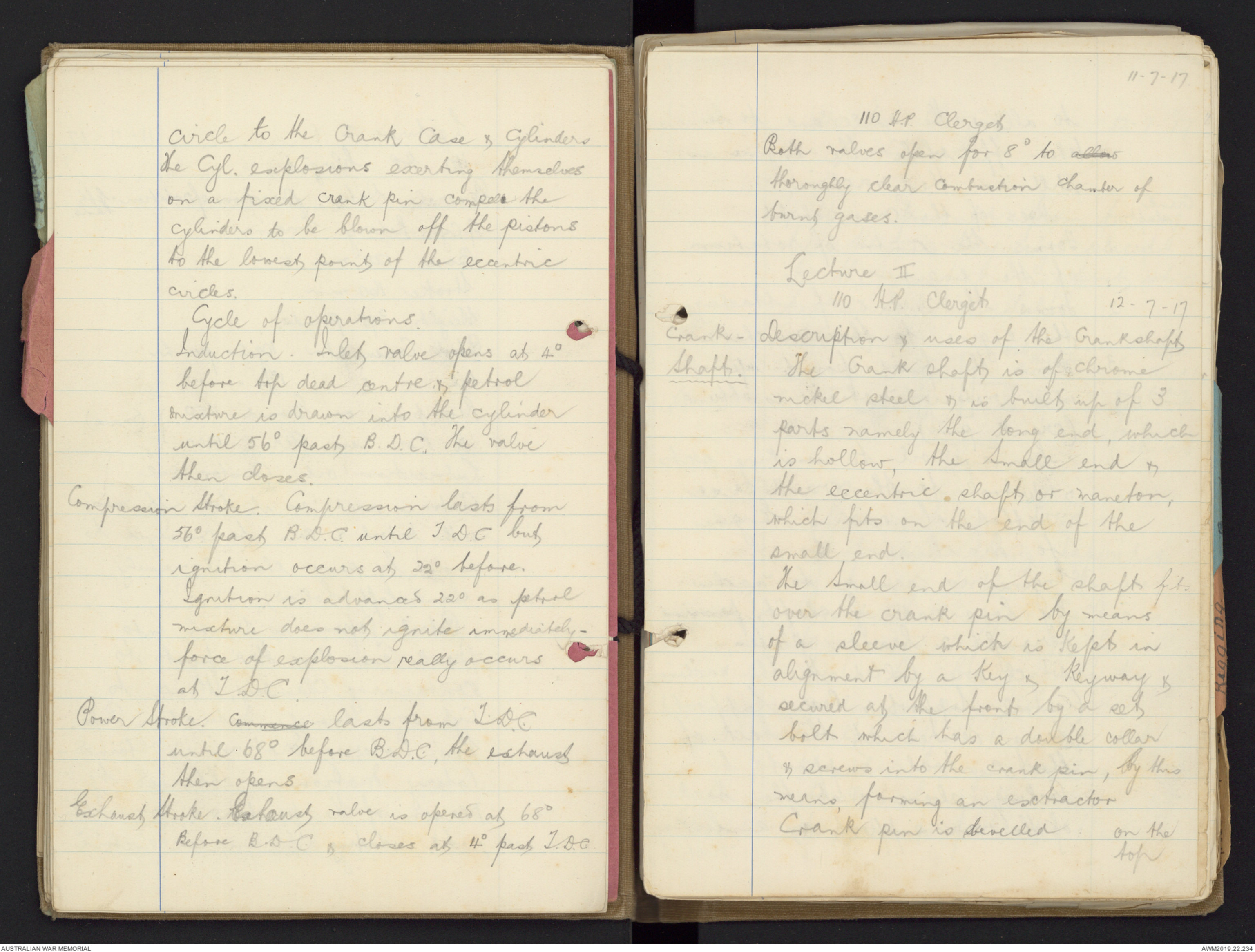
circle to the crank case & cylinders.
The Cyl. explosions exerting themselves
on a fixed crank pin compels the
cylinders to be blown off the pistons
to the lowest point of the eccentric
circles.
Cycle of operations.
Induction. Inlet valve opens at 4o
before top dead centre & petrol
mixture is drawn into the cylinder
until 56o past B.D.C. The valve
then closes.
Compression Stroke. Compression lasts from
56o past B.D.C. until T.D.C. but
ignition occurs at 22o before.
Ignition is advanced 22o as petrol
mixture does not ignite immediately -
force of explosion really occurs
at T.D.C.
Power Stroke. commence lasts from T.D.C.
until 68o before B.D.C., the exhaust
then opens.
Exhaust Stroke. Exhaust valve is opened at 68o
Before B.D.C. & closes at 4o past T.D.C.
110 H.P. Clerget
Both valves open for 8o to allow
thoroughly clear contraction chamber of
burnt gases.
Lecture II
110 H.P. Clergèt 12.7.17
Crank - Description & uses of the Crankshaft
Shaft The Crank shaft is of chrome
nickel steel & is built up of 3
parts namely the long end, which
is hollow, the Small end &
the eccentric shaft or maneton,
which fits on the end of the
small end.
The small end of the shaft fits
over the crank pin by means
of a sleeve which is kept in
alignment by a key & keyway &
secured at the front by a set
bolt which has a double collar
& screws into the crank pin, by this
means forming an extractor
Crank pin is levelled on the
top
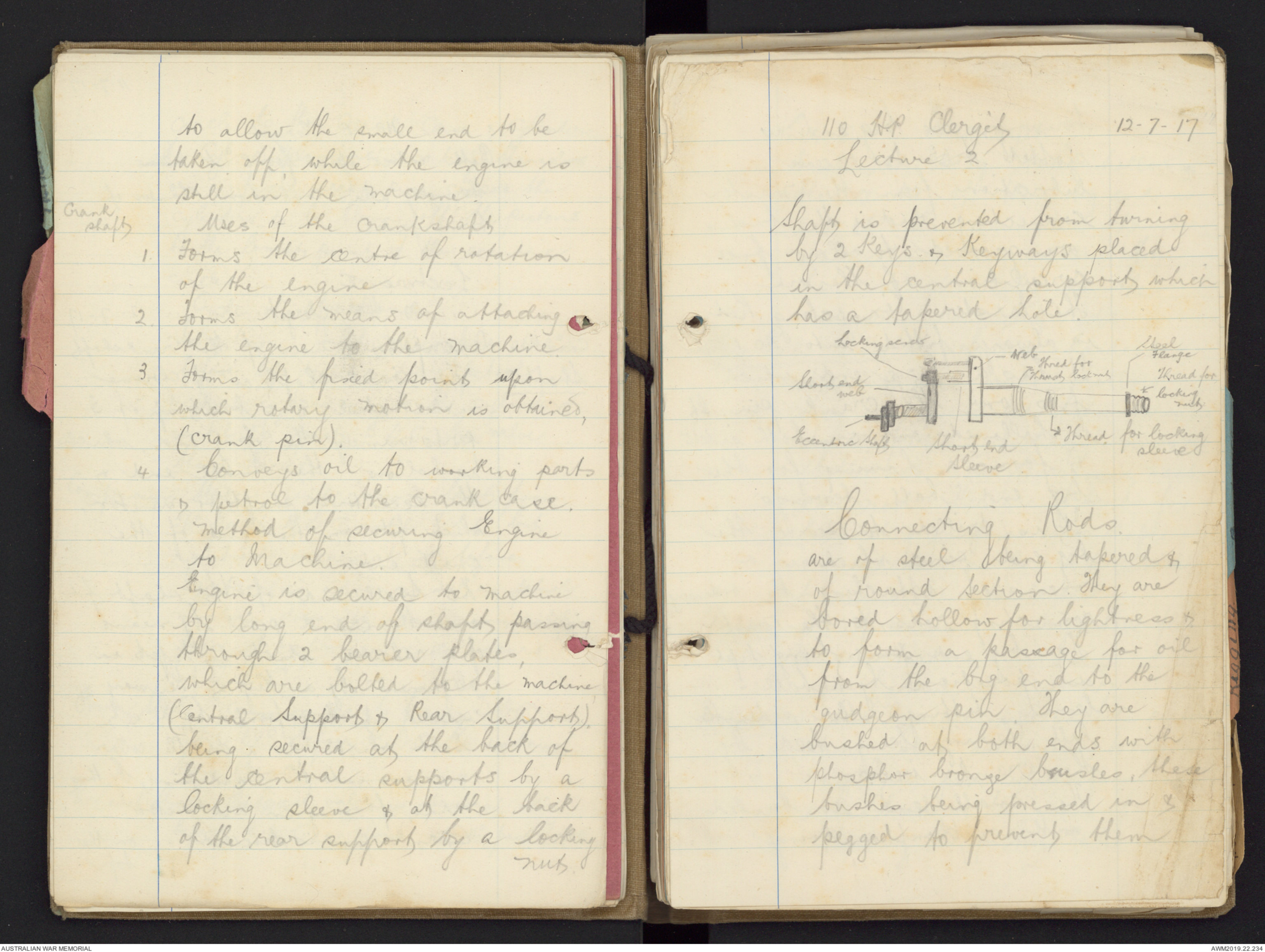
to allow the small end to be
taken off, while the engine is
still in the machine.
Crank shaft Uses of the Crankshaft
1. Forms the centre of rotation
of the engine
2. Forms the means of attaching
the engine to the machine.
3 Forms the fixed points upon
which rotary motion is obtained,
(crank pin).
4 Conveys oil to working parts
& petrol to the crank case.
Method of securing Engine
to Machine.
Engine is secured to machine
by long end of shaft passing
through 2 bearer plates,
which are bolted to the machine
(Central Support & Rear Support).
being secured at the back of
the central supports by a
locking sleeve & at the back
of the rear supports by a locking
nut.
110 H.P. Clergèt 12-7-17
Lecture 2
Shaft is prevented from turning
by 2 keys & keyways placed
in the central support which
has a tapered hole.
Diagram ~ see original document
Connecting Rods.
are of steel being tapered &
of round Section. They are
bored hollow for lightness &
to forma passage for oil
from the big end to the
gudgeon pin. They are
bushed at both ends with
phosphor bronze bushes, these
bushes being pressed in &
pegged to prevent them
turning. The big end is
slotted till to receive
lubrication from the master
connecting rod & the bushes
are grooved to allow free
circulation of the oil.
The Master Connecting Rod
is always fitted into No 1 Cyl.
It has a large end which
fits over the crank pin. It
is hollowed out on both sides
& forms a housing for the
big end ball-bearings.
It is drilled to receive the
big end pins which is a
means of attaching the ordinary
connecting rods to the master
The big end pins being kept
in position by a ball-bearing
fitting either side, the
ball bearings being held by
the crank web.
The small end is bushed
with a phosphor bronze
12.7.17
Lec II 110 H.P. Clergèt
bush rod being bored hollow. &
The centre of the big end is
called the annular chamber
lubrication being delivered from
here through holes to the
ordinary connecting rods
Big End Pins are of case - hardened
steel & are made hollow
They are prevented from turning
by a feather which fits into a
feather-way on the front master
Con. rod. They are grooved for
lubricating purposes & are so shaped at
one end to allow them to be extracted
by means of a special tool.
Pistons are of aluminium alloy & have flat
concave heads
Lecture 3 14-7-17
Pistons (Contd) Two lugs are cast on the piston
skirt, which are drilled to receive
the gudgeon pin which forms a
cross head & the means of
attaching the piston to the con. rod
Clergèt. Lecture III 14-7.17
Pistons. The piston skirt is cut away on
one side to allow them to clear
each other at B.D.C. This cut away
portion is always placed at the
rear. This is to have a stronger side
of side skirt on pushing side &
allow lubrication on rear which
is not so efficiently cooled.
Piston Rings 5 rings are fitted to the piston,
2 being obturator & 3 ordinary piston
rings. The obturator rings are
fitted at the top of piston, both
rings fitting in the same groove,
one over the other. They are
made of 70% copper & 30%
Silver. They are L. Section
split rings. They are fitted to
the piston to follow the distortion
of the cylinder caused through
uneven cooling & maintain
compression. Gaps to be
always placed at the
leading or cool side of cyl.
110 H.P.Clergèt.
Lecture III 14-7-17
and to be placed three c.m. apart.
Three Grooves are cut lower down
the skirt to accommodate the ordinary
Piston Rings these being made
of cast iron & their Gaps placed
equi-distant round the piston.
They are fitted to assist compression
& to evenly distribute lubrication
on the cyl. walls which comes thro'
holes drilled immediately below the
last groove on the piston skirts.
Gudgeon Pins are of case hardened steel & are
parallel being made solid. They are
secured by a set screw passing thro'
a hole in the lug & screwing into the
gudgeon pin, set screw being
secured by a split steel ring passing
thro' a hole in the head &
clamping around the lug.
Crank Case is a dropped steel forging & is
made in two halves, cylinders being
cho clamped between & the
 Marisa Bortolotto
This transcription item is now locked to you for editing. To release the lock either Save your changes or Cancel.
This lock will be automatically released after 60 minutes of inactivity.