Service notebook of Harold Gordon Cornell - 1917 - Part 4
120 H.P. Beardmore
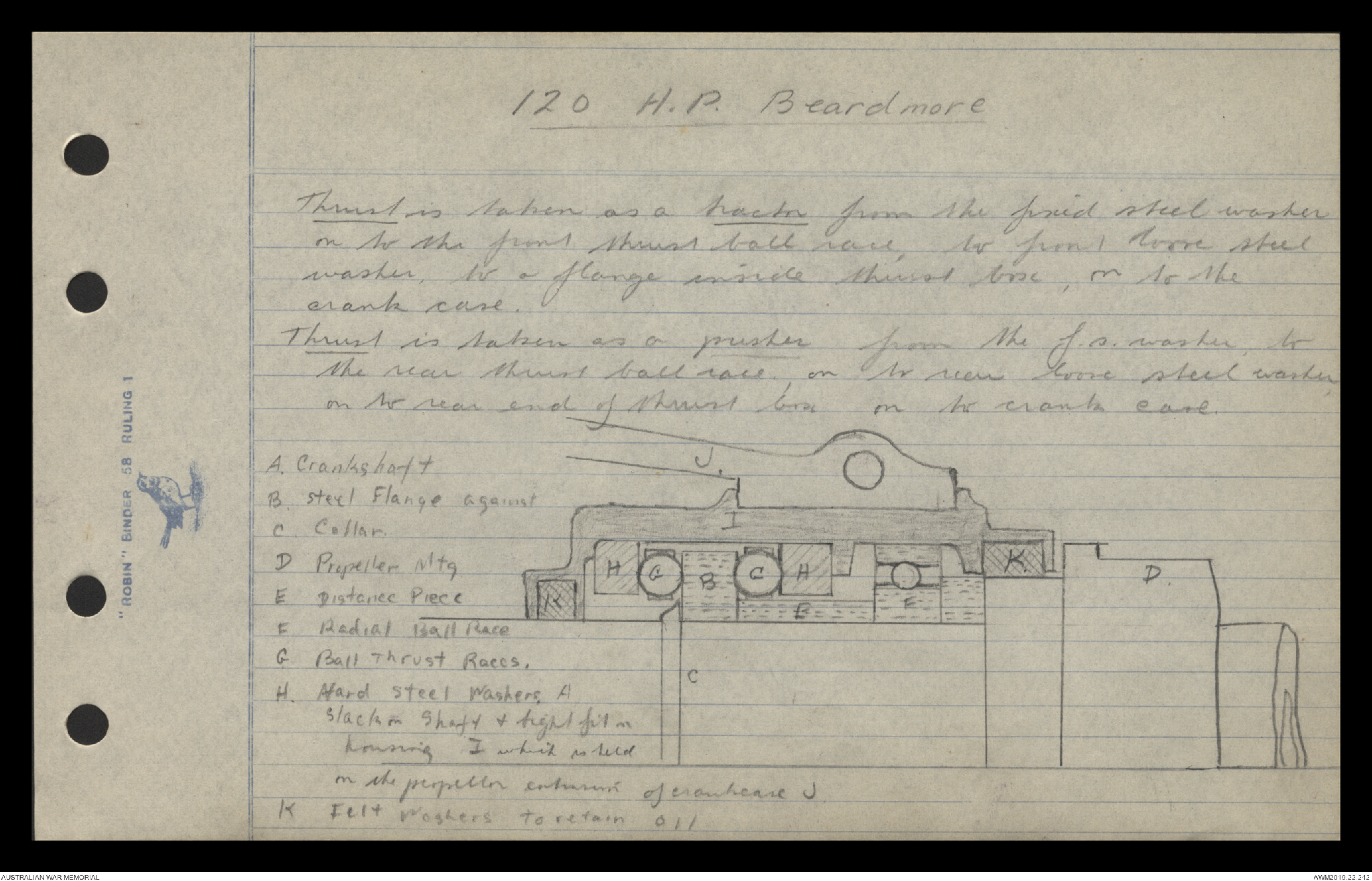
Thrust is taken as a tractor from the fired steel washer
on to the front thrust ball race, to front bore steel
washer, to a flange inside thrust box, on to the
crank case.
Thrust is taken as a pusher from the f.s. washer, to
the rear thrust ball race, on to rear loose steel washer,
on to rear end of thrust box on to crank case.
[[Hand drawn diagram containing letters corresponding to descriptions]]
A. Crankshaft
B. Steel Flange against
C. Collar.
D. Propeller mtq
E. Distance Piece
F. Redial Ball Race
G. Ball Thrust Races.
H. Hard Steel Washers
Slack on Shaft & tight fit on
housing I. which is held
on the propellor casement of crankouse J.
K. Felt Washers to retain 011
[[Hand drawn diagram]]
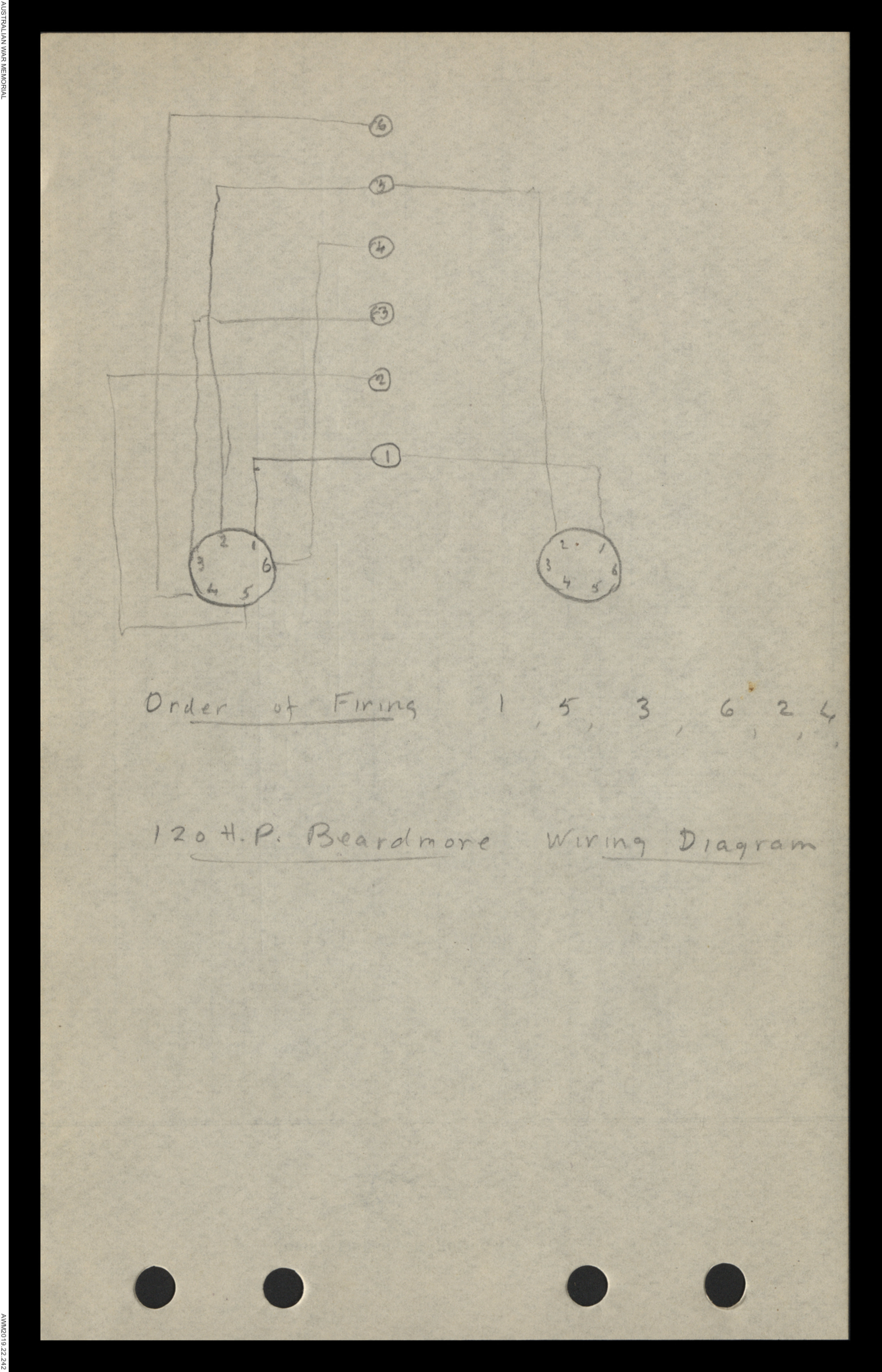
Order at Firing 1, 5, 3, 6, 2, 4,
120 H.P Beardmore Wiring Diagram
120 H.P. Beardmore.
Lubrication is partly by force, splash, & grease. Force
is by the Bosch 6 way oil-pump, through internal
pipes to main bearings, cylinder walls & thrust
box. The flow of oil, can be regulated by means
of adjusting [[?]] on the top of the Bosch lubricator,
Splash is by the big ends having a scoop fitted
on the bottom half of the big end bearing which
dips into its own compartment in the sump when
rotating. Grease to all external working parts
all driving wheels, including water pump spindle, & small
grease caps for each rocking level. The sump requires
4 pints of fresh oil after the engine has been run
12 hours. After the oil has been used for this length
of time it loses its body, so is all drained out, by
removing the 6 brass plugs in the bottom of the sump.
The crank case is then thoroughly cleaned out with
paraffin & fresh oil put in, from ½ pint to 3/6 pint
being placed in each compartment. The oil can be
poured either through the breathers or by raising the can
angle lever cords.
120 H.P. Beardmore
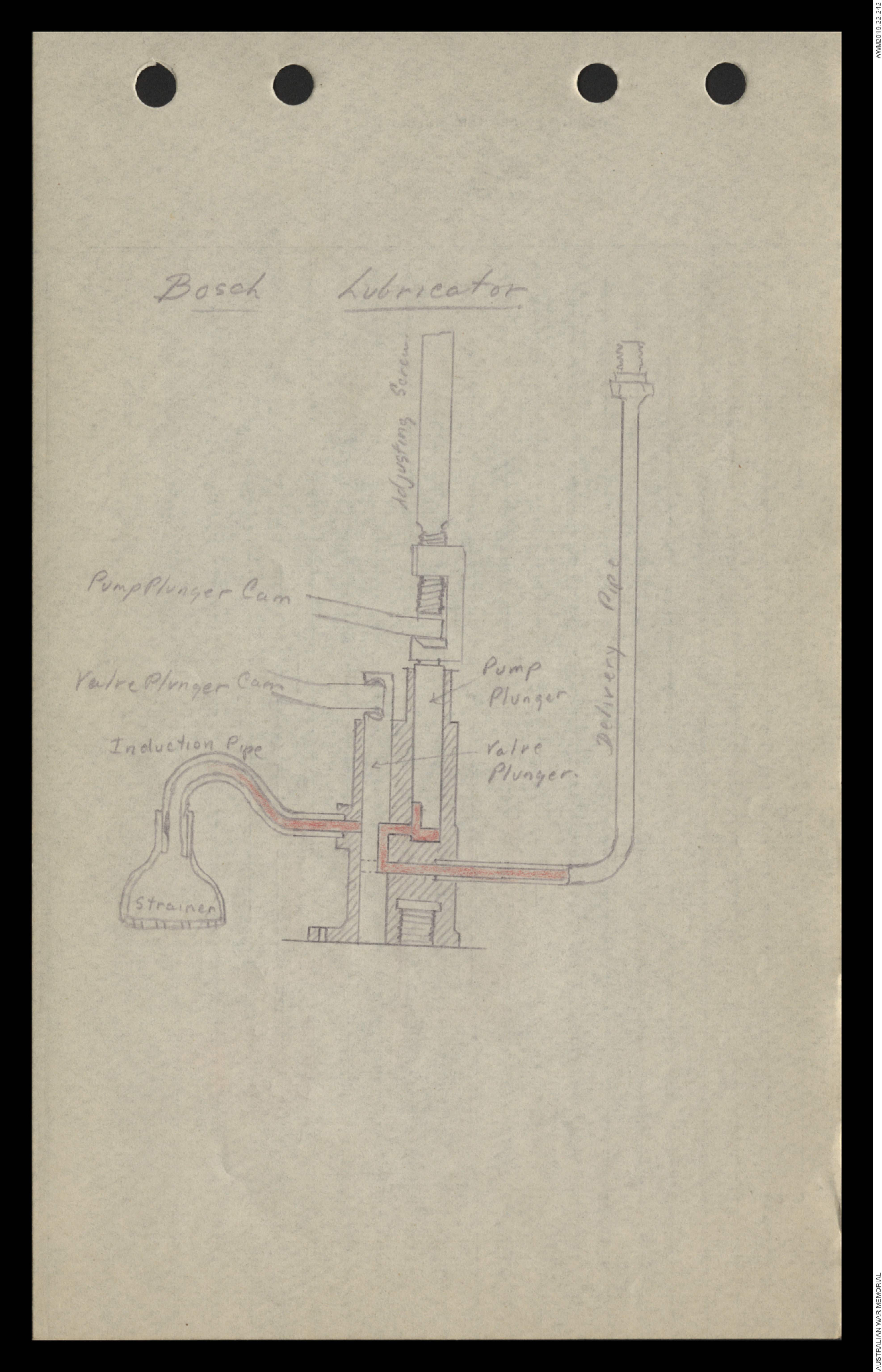
The Bosch Lubricator The pump case is kept filled
with oil by gravity from the oil tank; the pump
spindle is driven at engine speed, but is
internally geared down to 1/25 engine speed by
means of a [[?]] & sector gearing. Two cams
are mounted on a spindle, the upper & longer cam
activating the six pump plungers, the lower & smaller
one the six valve plungers, thus giving six
deliveries of oil.
Four strokes of the pump (1) The valve plunger is
raised by a cam (2) The pump plunger is raised drawing
oil into the pump barrel through ports via hole
in the valve plunger (3) The valve plunger is depressed
cutting off the supply of oil, & simultaneously by
means of a flat on the side of the valve plunger
opens the way from pump plunger to delivery pipe
(4) Pump plunger is depressed giving oil out of the
pump barrel via the flat to the delivery pipes.
No. 1 delivery pipe goes to No. 1 Major Bearing & Thrust Bearing
No. 2 " " " " No's 1, 2, 3 Cylinder Walls
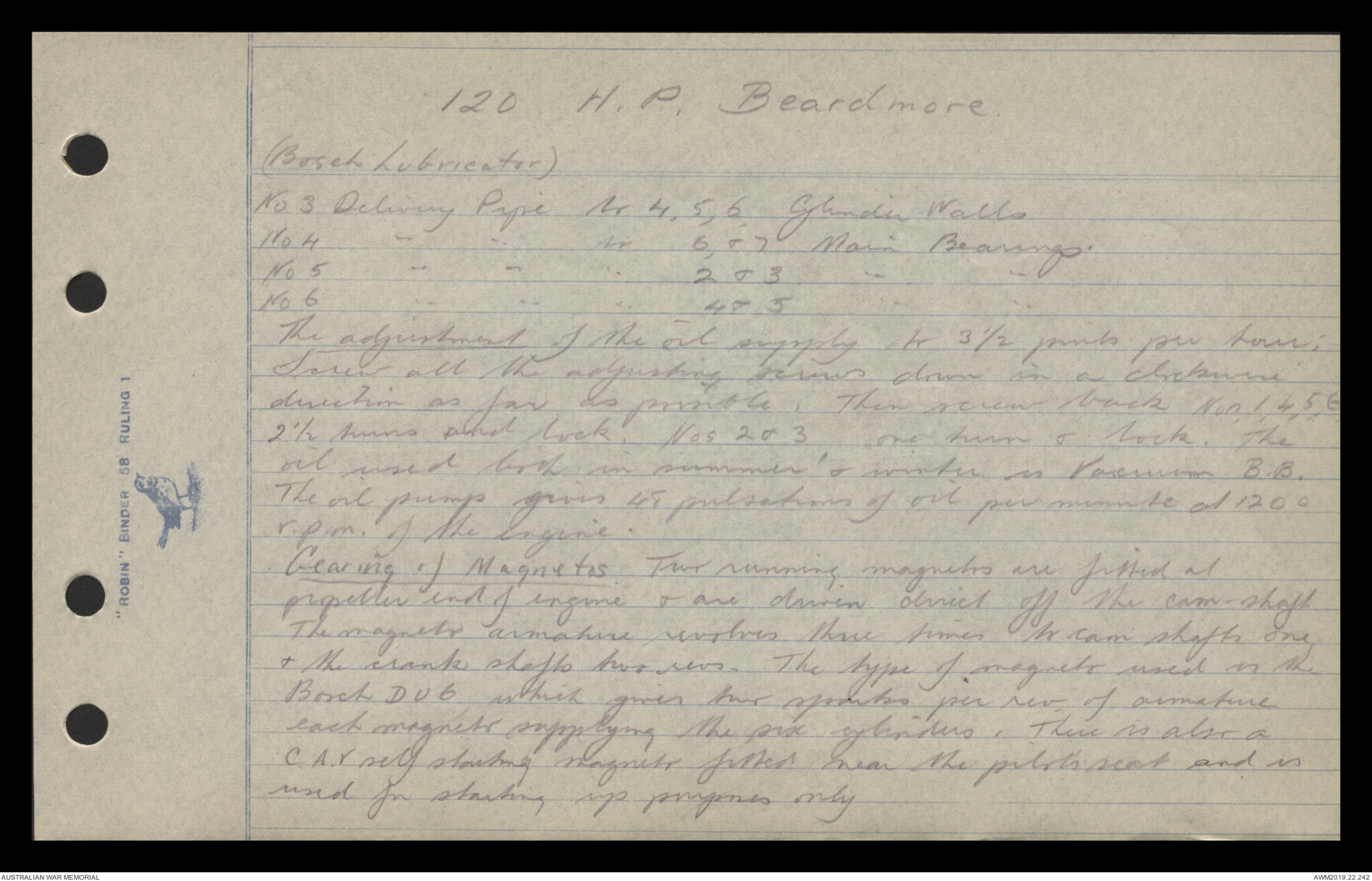
120 H.P. Beardmore.
(Bosch Lubricator)
No. 3. Delivery Pipe to 4,5,6 Cylinder Walls
No. 4. " " " 6 & 7 Main Bearings.
No. 5. " " " 2 & 3 " "
No. 6. " " " 4 & 5 " "
The adjustment of the oil supply to 3½ pints per hour;
Screw all the adjusting screws down in a clockwise
direction as far as possible. Then screw back Nos. 1, 4, 5, 6,
2½ turns and lock. Nos 2 & 3, one turn & lock. The
oil used both in summer & winter is [[Vacuum?]] B.B.
The oil pump gives 48 pulsations of oil per minute at 120°
r.p.m. of the engine.
Gearing of Magnetos. Two running magnetos are fitted at
propeller end of engine & are driven direct off the cam-shaft.
The magneto armature revolves three times to cam-shafts one
& the crankshafts two revs. The type of magneto used is the
Bosch D V 6 which gives two spurts per rev of armature
each magneto supplying the six cylinders. There is also a
C.A.V. self starting magneto fitted near the pilots seat and is
used for starting up purposes only.
Bosch Lubricator
[[Hand drawn detailed diagram]]
- 120 H.P. Beardmore.
Wiring of C.A.V. Self Starting Magneto
Connect with H.T. wire. the large terminal on the C.A.V. to
central terminal on R.H. Magneto & connect small terminal
on the C.A.V. to the switch & from switch to earth,
To Start Engine:-
See that all switches off, turn petrol on with throttle ¼ open,
ignition lever retarded & main air intake ports closed; then
turn propeller round several revs, to suck a good
mixture into the cylinders, always leaving the propeller
just over the compressor stroke, then after being given
all clear, switch on all magnetos, & turn small handle
on C.A.V. until engine is started; after engine is started
switch off C.A.V. & run the engine at about 600 revs
per minute until engine is warmed up.
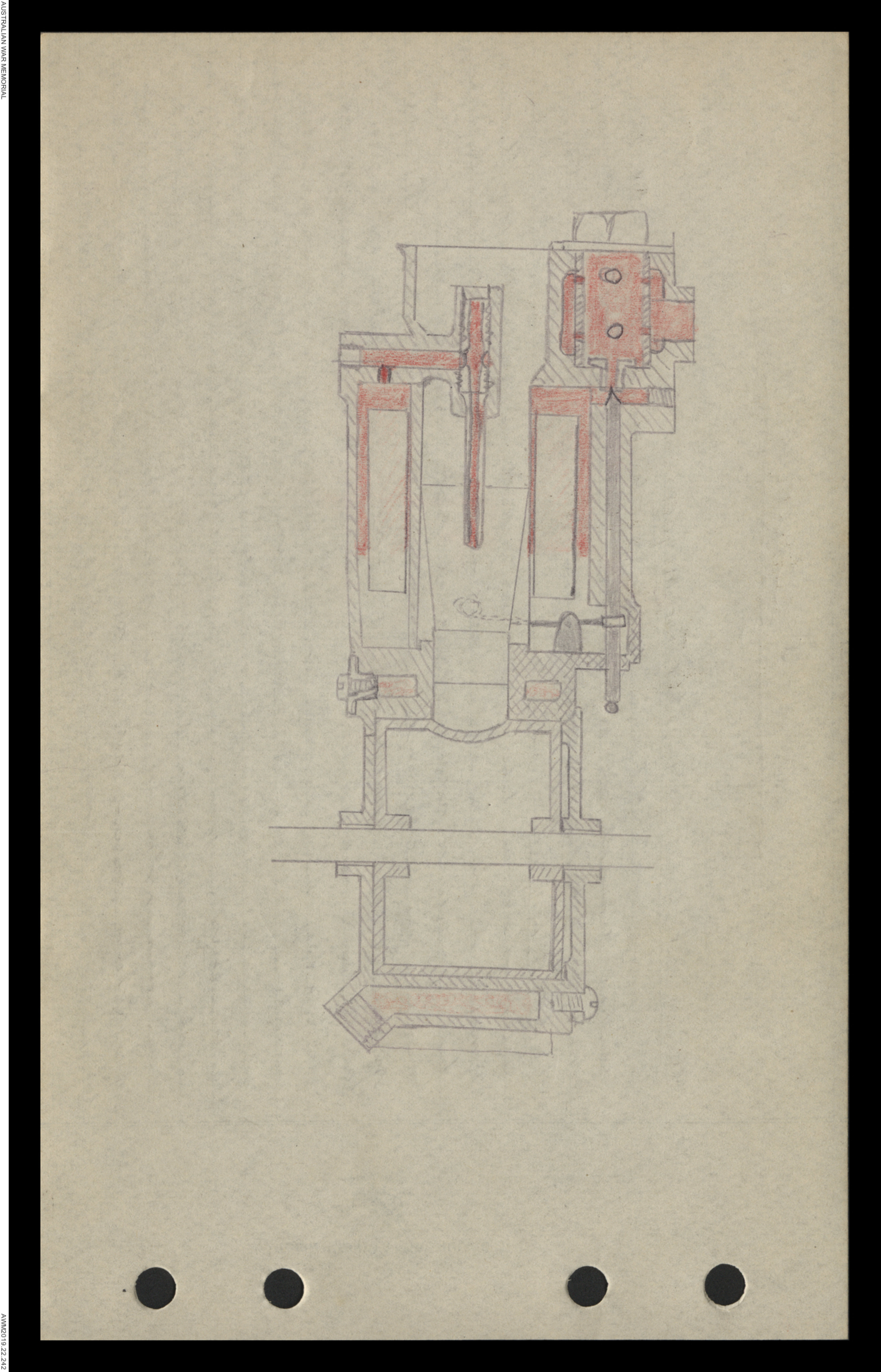
Carburetters. There are 2 carburetters, which are Beardmore
design & [[?jacketed]], each one supplying 3 cylinders. They are
each made with a single fit, the control being by means
of a rotary sleeve which is so designed to keep a ratio
of petrol & air constant at all speeds of the engine .
[[Detailed Hand Drawn Diagram]]
- 120 H.P. Beardmore -
Tracing petrol into Engine. The petrol is forced by
pressure from the main tank into the filter up the
middle valve into the circular float chamber. The
float rises against balance weights & cuts off the supply
when the petrol reaches its proper level. Petrol is
drawn out of the jet & also air from the main air inlet
by suction from the engine & is drawn through the
choke tube into the mixing chamber where it mixes
with the extra air from the extra air inlet & is
quickly vaporised by the help of hot water round the
gaskets, from here it is controlled by the rotary sleeve
and passes out in the form of a vapour through the
induction pipes & inlet valves into the cylinders
Strength of Leaf Spring 46 lbs each side
Rev Counter driven by shaft through top of lubrication case.
Bombs
Fuse, Bomb, D.A. No. 1 MK I (Nose Fuse for 112 lb
HERL Bomb MK III )
On release from the carrier the safety collar is withdrawn
allowing the vane to rotate, which during
40ft. of fall screws up until the strike on just off
the detonator. On impact; there is a pressure exerted
on the pressure plate, which shears two copper joins,
allowing the 'striker' to fire the detonator. This in
turn fires a small charge of C.E. (Corporation Englemore)
which blows out the end caps of the fuse & fires
the main charge.
Safety Devices (1) Transit pin (2) Safety Collar
(3) Red, safety setting line.
(4) Copper Shearing Pins.
Pistol Tail, for H.F.R.L. Bomb
On release from the carrier the safety clip is
withdrawn allowing the vane to rotate, which during
40ft. of fall screws off allowing the sticker & nut to fall on
to a weak spiral spring which holds it off a detonator
On impact, the striker & nut are shot down, compress the
 Sam scott
This transcription item is now locked to you for editing. To release the lock either Save your changes or Cancel.
This lock will be automatically released after 60 minutes of inactivity.