Service notebook of Harold Gordon Cornell - 1917 - Part 19
(13)
The object of this is to detect "Sparking"
Any leakage detected is to be remided xxxxxxx
immediately.
LOG. The operator i/c machines will keep a
log book setting forth details as under
which will be recorded daily.
(14)
General Routine
When a machine is detailed for wireless
practice the operator i/c machines will see
that everything appertaining to the wireless
installation is is readiness at least 1/2 hour
before specified time of flight.
Before the machine leaves the ground he will
explain the use of the safety plug to the
occupants of the machine.
When the machine leaves the ground the
operator xx i/c machines will "tune in"
at the aerodrome wireless station and put
out the signal "K" to proceed if wireless is
working properly.
Directly a machine carrying wireless returns to
aerodrome he will go to it at once
overhaul set clean contacts &c.
The operator i/c machines is ON DUTY until
all machines carrying wireless are in
(15)
HINTS FOR WIRELESS OPERATORS.
The Stirling Transmitter.
1 The platinum contacts must be absolutely
flat and true when they meet to avoid loss
of efficiency in set and eventual
destruction of contacts.
2 The iron core should be so arranged
as to get an even pull on the blade.
The Core must be true. If necessary
to true up core file it.
4 The rubber adjusting stud.
When this is screwed up more tension
is put on the blade. This nut alters the
current through set.
MINIMUM CURRENT Screwed down
MAXIMUM CURRENT Screwed up.
x3 Adjusting note Remember that the nearer
the core the blade is adjusted the higher
the note.
5 The spark gap The aluminium gets "Pitted"
and the probability arises of uneven
sparking which spoils note.
The spark gap device needs constant trueing
and polishing.
6 The spark gap chamber becomes filled with
metal dust and this may cause "arc-ing"
To avoid losses due to arc-ing occasionally
clean and shellac spark gap chamber.
7 Tuning clips. Observe carefully that these do
not become "spread" and so "short" the in
inductance coils.
(16)
8 Adjusting set You want to get as much
current as possible through set without xxx
excessive sparking at the contacts.
The current should be of a value as
nearly approaching 5 amps as possible.
9 To adjust spark gaps remember that the
wider the spark gap the longer the time
the condenser takes to charge and the
greater the sparking at the contacts.
Remember not to set the spark gap at its
maximum because the set has usually to work
for several hours. Adjust the gap rather on
the small side.
take steps to avoids excessive sparking
at the contacts.
WIRING MACHINES.
Use U3 for key leads
" P11 for earth leads
" P3 for aerial lead.
AERIAL WIRE.
When unwinding aerial wire R4 from a drum
always let drum unroll and so avoid "kinking"
the wire. Losses of aerials are often due to
"kinked" or bruised wire.
Dont use pliers too much when twisting up R4
use your fingers and thus avoid kinking
bruising and similar damage due to twisting.
Dont bend the wire round the hook of the
aerial weight. It will soon wear there the use
of a brass thimble will tend to overcome this.
Issued by officer i/c Wireless
24th Wing R.F.C.
Spittlegate
SCHOOL FOR WIRELESS OPERATORS R.F.C. NOTES ON MK/3 TUNER etc.
1 Ordinary aerials are150 or 125 feet long from tuner to
free end.
(2) If your aerial is 150 ft long you will find the following
notes for "stand by" fairly exact. Place coupling at
loose and secondary condenser at 'O' in order to avoid
absorption of energy by secondary circuit. Place primary
inductance on stud 6. If you were attached to a squadron
whose wave lengths were 160 180 220 and 250 metres those
wave lengths would come in about 6 12 30 and 48 on the aerial
tuning condenser provided your aerial was of the above length
(150) ft. If your aerial is 125 ft long from tuner to free end
and the squadron wave lengths xxx are 140 180 and 220 metres
these will come in about 2 20 and 70 on the aerial tuning
condenser. If you compare the two sets of figures given
above you will see that the smaller aerial has considerably
less capacity than the larger aerial and this entails the
addition of greater capacity in the aerial tuning condenser
to cover a certain range of wave lengths. The above information makes the picking up of machines a very simple matter.
if you are attached to a field artillery or to 60pdr batteries
whose chief duties are firing upon NF or GF targets you will
be chiefly concerned with picking up area calls. For this
purpose you will use "stand by" side only and the aerial tuning
condenser must be kept constantly on the move over the number
of degrees necessary to cover the wave lengths in use on
your front.
(3) When you switch over for a shoot always try retuning your
primary by decreasing inductance and increasing aerial condenser.
Very often two or three studs of Primary Inductance and large
condenser will give the best results. The tuning of the
secondary is a very simple matter as you know from the position
of your aerial tuning condenser what wave length you are receiving
and you have only to read off the same wave length on the
Calibration card inside the tuner to get the correct adjustment
for the secondary circuit. If there are several alternative
readings given for a certain wave length on the calibration card
you should select that reading which gives the maximum inductance
combined with the minimum condenser to get the loudest signals
on the secondary.
(4) Crystals. Both perikon and carborundum give the best results
with a light contact. A sure sign of a dud operator is a collection
of crystal chippings underneath the perikon detector due to excessive
tension on the spring. If you can get no result out of the
carborundum it probably means that rust has formed on the
underneath of the steel blade or that 3 volts is insufficient to
reach the rectifying point of the particular crystal you are
using. The formation of rust must be avoided by polishing the
steel blade every day and the crystal can probably be made to
rectify by connecting all four cells in series. This will
give 6 volts in which to reach the rectifying point and will
be found effective in the great majority of cases. If the
Carborundum still refuses to rectify the signals you should
ask your squadron officer for another crystal.
If you are using 6 volts on the carborundum you should tap off
at 3 volts (i.e. 2 cells) for buzzer and this will make it
necessary to adjust your carborundum on a signal not on the
buzzer. To find the most sensitive point on a crystal by the
buzzer-- place coupling at loose and adjust your two circuits so
xxxx that they are badly out of tune. The signal can now only be
heard when the crystal is in really sensitive adjustment.
(5) The great secret of success in wireless is to keep all your
contacts and your instrument scrupulously clean, Remember that
dirty contacts intruduce unnecessary resistance into a circuit
where the total pressure is only a very small fraction of a volt.
such unnecessary resistance will cause weak signals and may
result in total failure. When you get to the front make up your
mind to wipe your instrument and all contacts over with a rag
at the close of each days work and to close the lid for the night.
A drop of petrol on a rag is of great assistance.
If the joint in your aerial where P-11 joins the R4 is not
soldered it must be cleaned at least once a week and carefully
protected by insulating tape.
xxxxxxxxxxxxxxx
xxxxxxxxxxx have been found useful:-
(1) xxxxx the coupling and make
"NOTES ON JAMBING"
The following hints have been found useful.:-
(1) Loosen the coupling and make sure that both your circuits
are dead in tune. Remember that when you vary the coupling
you automatically alter the capacities of both circuits
and both will require very s-light retuning.
(2) If this is insufficient retune the secondary by reducing the
inductance and increasing condenser. This tends to weaken
signals but sharpen tuning.
(3) Remarkable results can sometimes be obtained by placing
inductance switches so that they make contact with two studs at
once retuning the condensers at the same time. This should be
regarded as "freak" tuning" and should not be made standard
practice.
(4) Try varying potentiometer when using carborundum. You can
sometimes bring up your own signal and reduce others by this xxx
means.
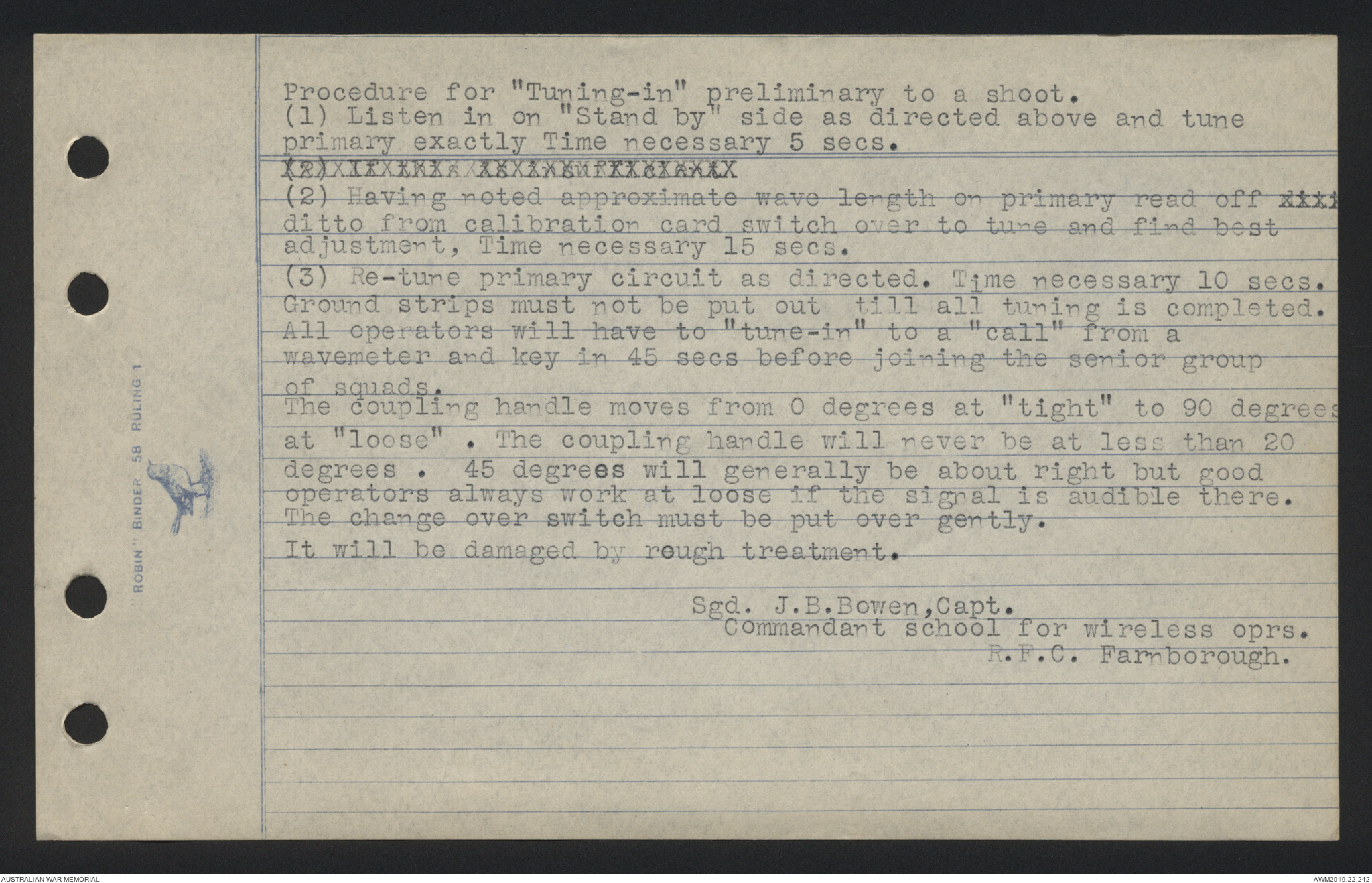
Procedure for "Tuning-in" preliminary to a shoot.
(1) Listen in on "Stand by" side as directed above and tune
primary exactly Time necessary 5 secs.
(2)xxxxxxxxxxxxxx
(2) Having noted approximate wave length on primary read off xxx
ditto from calibration card switch over to tune and find best
adjustment, Time necessary 15 secs.
(3) Re-tune primary circuit as directed. Time necessary 10 secs.
Ground strips must not be put out till all tuning is completed.
All operators will have to "tune-in" to a "call" from a
wavemeter and key in 45 secs before joining the senior group
of squads.
The coupling handle moves from 0 degrees at "tight" to 90 degrees
at "loose". The coupling handle will never be at less than 20
degrees. 45 degrees will generally be about right but good
operators always work at loose if the signal is audible there.
The change over switch must be put over gently.
It will be damaged by rough treatment.
Sgd. J.B. Bowen, Capt.
Commandant school for wireless oprs.
R.F.C. Farnborough.
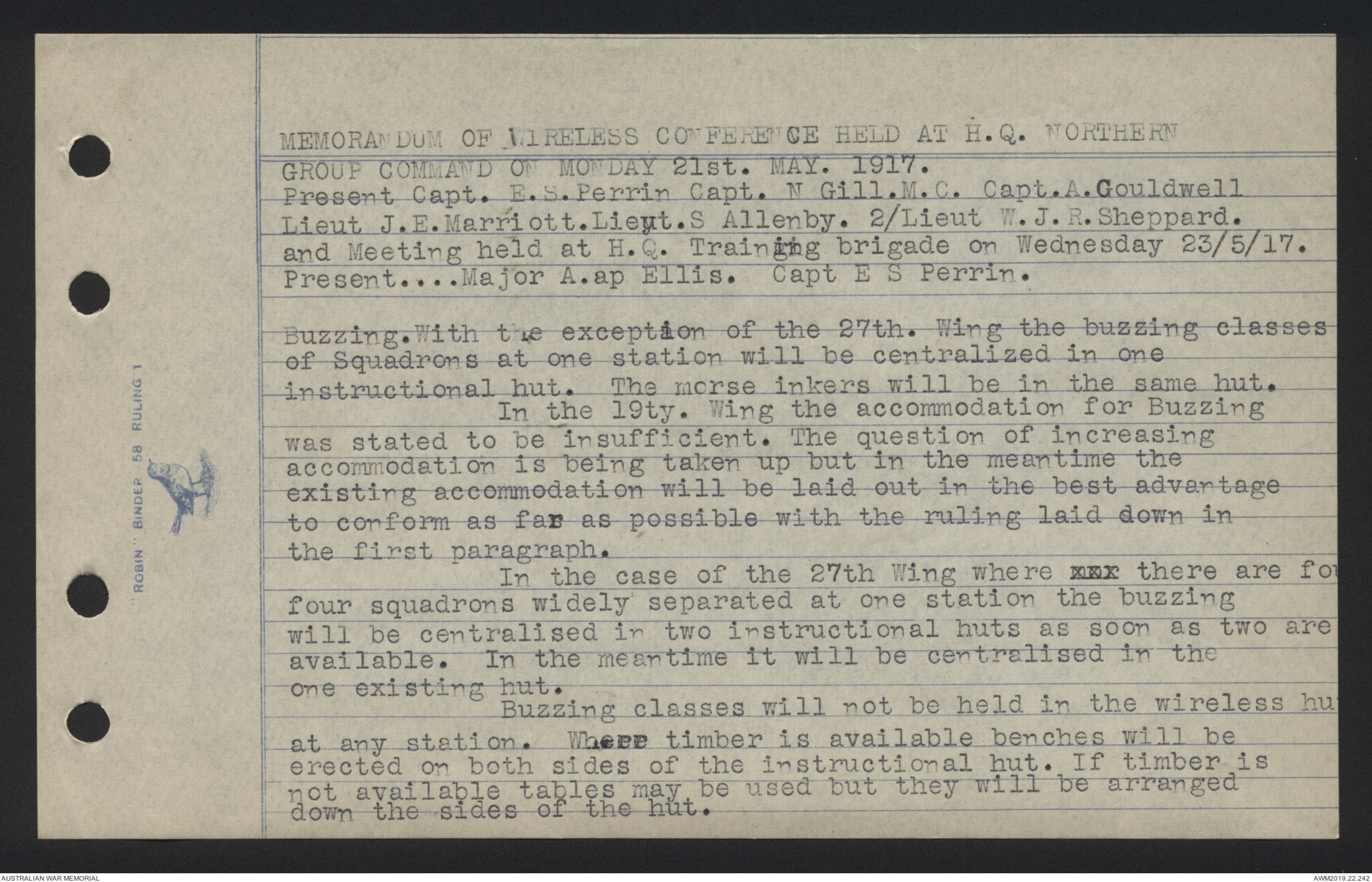
MEMORANDUM OF WIRELESS CONFERENCE HELD AT H.Q. NORTHERN
GROUP COMMAND ON MONDAY 21st MAY 1917.
Present Capt. E.S. Perrin Capt. N. Gill. M.C. Capt. A. Gouldwell
Lieut J.E. Marriott. Lieut. S. Allenby. 2/Lieut W.J.R. Sheppard.
and Meeting held at H.Q. Training brigade on Wednesday 23/5/17.
Present ..... Major A.ap Ellis. Capt E S Perrin.
Buzzing. With the exception of the 27th. Wing the buzzing classes
of Squadrons at one station will be centralized in one
instructional hut. The morse inkers will be in the same hut.
In the 19ty. Wing the accommodation for Buzzing
was stated to be insufficient. The question of increasing
accommodation is being taken up but in the meantime the
existing accommodation will be laid out in the best advantage
to conform as far as possible with the ruling laid down in
the first paragraph.
In the case of the 27th Wing where xxx there are fo
four squadrons widely separated at one station the buzzing
will be centralised in two instructional huts as soon as two are
available. In the meantime it will be centralised in the
one existing hut.
Buzzing classes will not be held in the wireless hut
at any station. Where timber is available benches will be
erected on both sides of the instructional hut. If timber is
not available tables may be used but they will be arranged
down the sides of the hut.
 Sam scott
This transcription item is now locked to you for editing. To release the lock either Save your changes or Cancel.
This lock will be automatically released after 60 minutes of inactivity.