Service notebook of Harold Gordon Cornell - 1917 - Part 16
Rigging - Theory of Flight
Drift of 3 types.
(1) Active Drift. (produced by lifting surfaces)
(2) Passive Drift (produced by all non lifting pistons)
(3) Skin Friction (due to bad taping, flabby fabric)
Lift / Drift Ratio expresses the efficiency of a machine.
(Effected by six strings.
(1) Velocity. (stream lining to get over part of passive drift)
(2) Incidence (∠ between chord & direction of an attack)
angle varies with wt to be carried, climbing velocity
ratio, thrust.
(3) Camber (to reduce drift on under side enables air to glide
off plane, top camber helps to stream line
the drift area at rear of plane.)
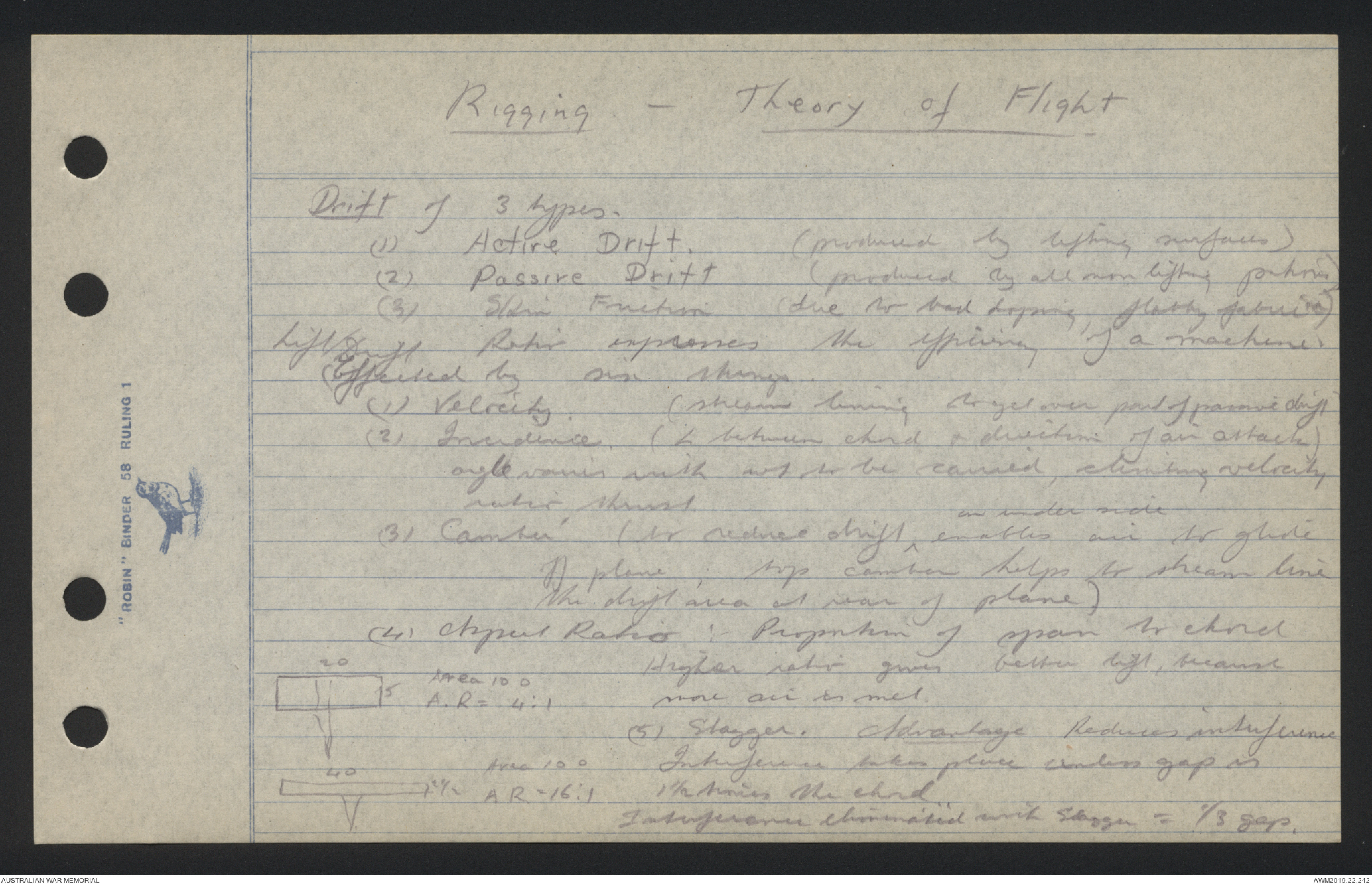
(4) Aspect Ratio: Proportion of span to chord
Diagram - see original document
Higher ration gives better lift, because
more air is met.
(5) Stagger. Advantage Reduces interference
Interference takes place unless gap is
1 ½ times the chord.
Interference eliminated with Stagger = ⅓ gap.
Rigging - Theory of Flight
(6) Horizontal Equivalent
H.E. when machine is flying
H.E. diagram - see original
level is not equal to length of plane, when
machine banks slightly, H.E. of one plane
increases & other decreases. & so tends to
right machine. Hence dihedral decreases efficiency
but increases stability.
Margin of Power Power of available over that necessary
to maintain horizontal flight
Margin of Lift Height a plane can attain in given time from
a given altitude (Decreases as machine reaches
higher altitudes)
Minimum Angle of Incidence Lowest angle at
which flight can be maintained.
Maximum Angle of Incidence Greater ∠ at which etc.
Optimum Angle of Incidence. Angle at which
Lift Drift ratio is highest
Best Climbing Angle approximately ½ way between
maximum & optimum.
- Theory of Flight -
Stability of 3 types Stable, unstable, neutral.
A body is stable when it tends to return to its
original position after being acted on by an outside
force; unstable when it tends to move further
& further from its original position; neutral stability
when it xx remains in any position in which it
is put.
On a flat surface centre of pressure moves
forward as incidence increases, in cambered surface
backward.
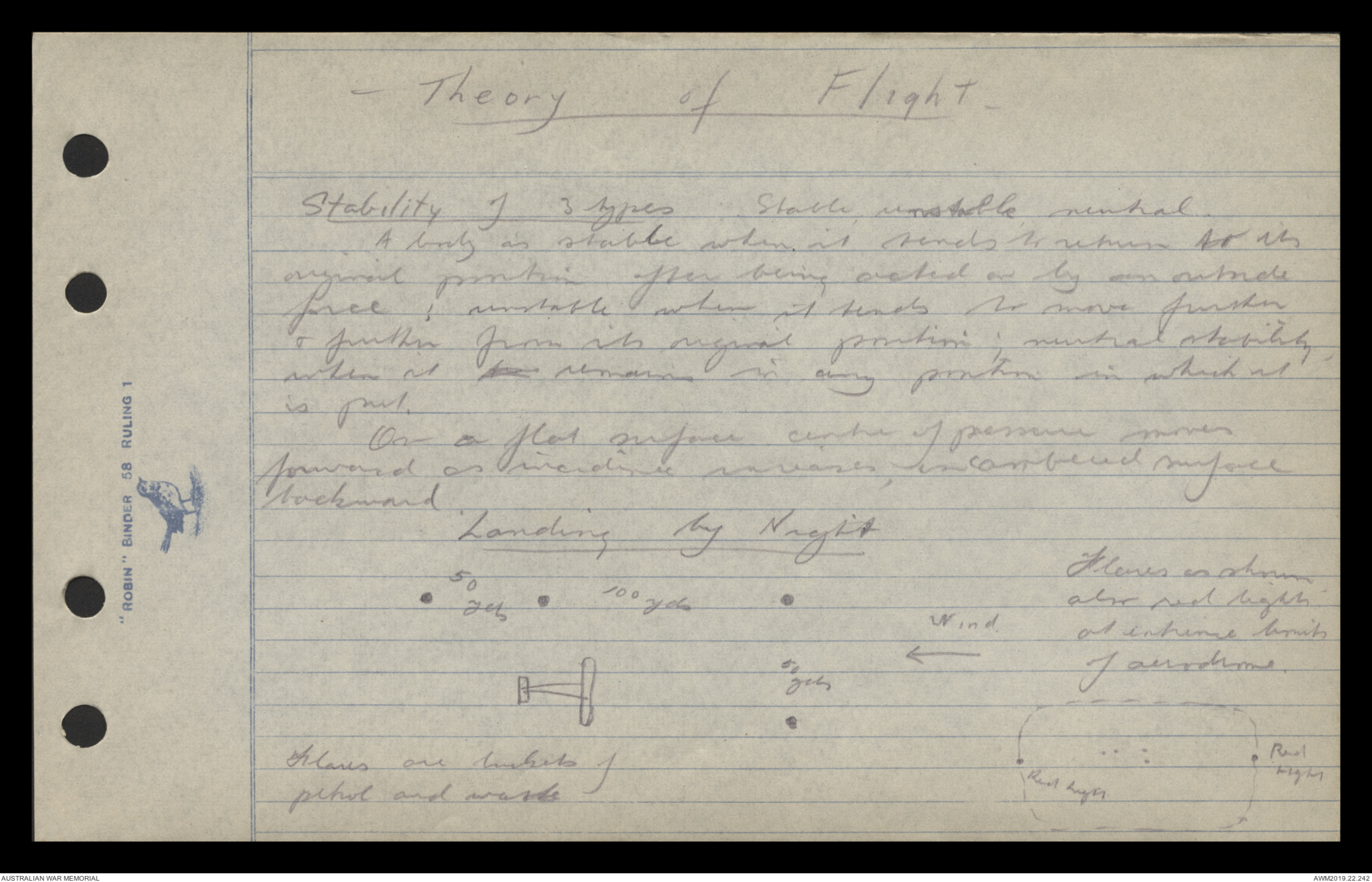
Landing by Night
Diagram - see original document
Flares as shown
also red lights
at extreme limits
of aerodrome
Flares are buckets of
petrol and waste
- Theory of Flight -
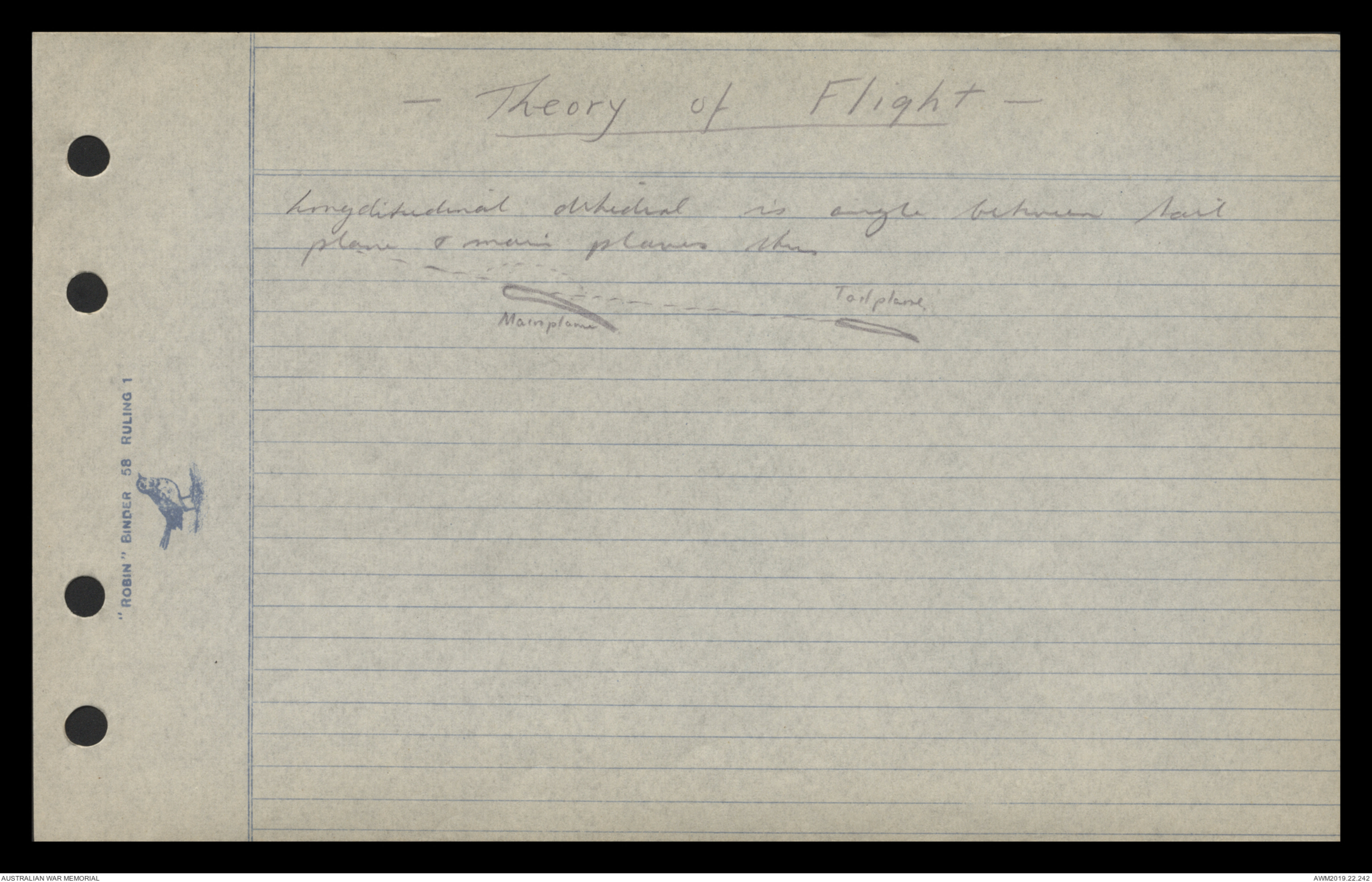
Longditudinal dihedral is angle between tail
plane & main planes thus
Diagram - see original document
1.
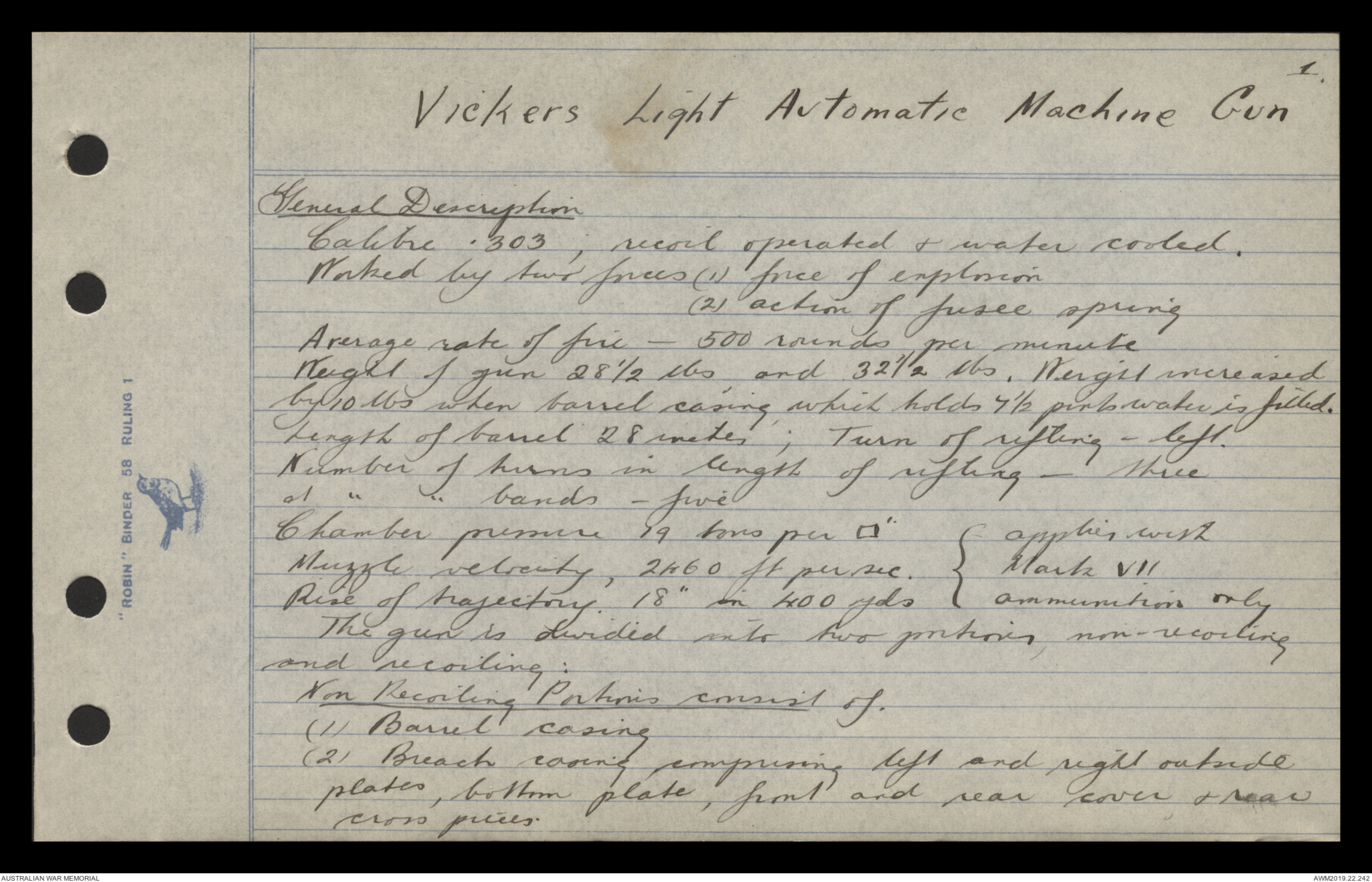
Vickers Light Automatic Machine Gun
General Description
Calibre .303; recoil operated & water cooled.
Worked by two forces (1) force of explosion
(2) action of fusee spring
Average rate of fire - 500 rounds per minute
Weight of gun 28½ lbs, and 32½ lbs. Weight increased
by 10 lbs when barrel casing, which holds 7½ pints water is filled.
Length of barrel 28 inches; Turn of rifting - left.
Number of turns in length of rifting - three
& " " bands - five
Chamber pressure 19 tons per □ " {applies with
Muzzle velocity, 2460 ft per sec. { Mark VII
Rise of trajectory. 18" in 400 yds { ammunition only
The gun is divided into two portions, non-recoiling
and recoiling:
Non Recoiling Portions consist of.
(1) Barrel casing
(2) Breach casing comprising left and right outside
plates, bottom plate, front and rear cover, & rear
cross pieces.
2.
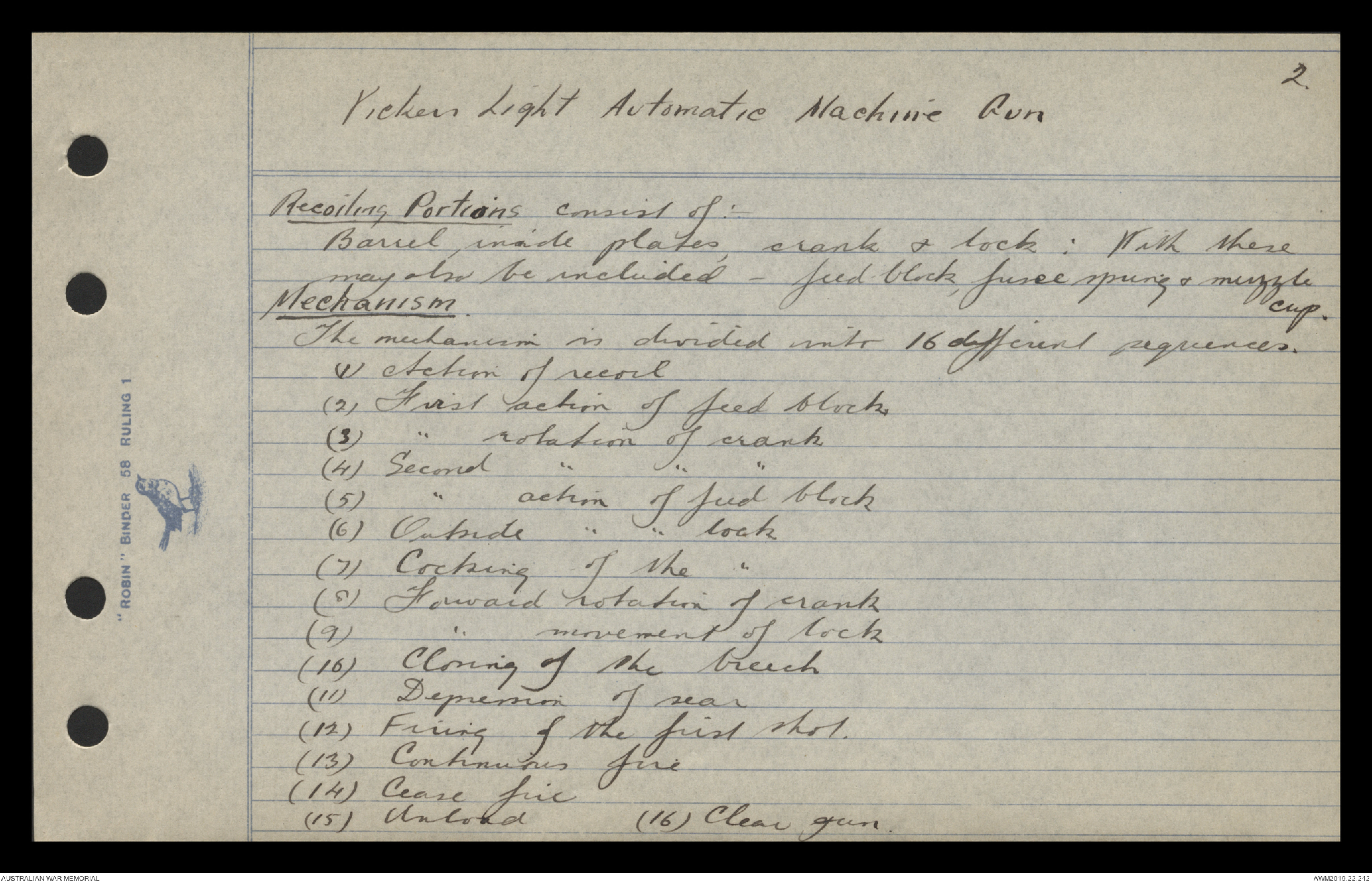
Vickers Light Automatic Machine Gun
Recoiling Portions consist of:
Barrel inside plates, crank & lock: With these
may also be included - feed block. fusee spring & muzzle cup.
Mechanism.
The mechanism is divided into 16 different sequences.
(1) Action of recoil
(2) First action of feed block
(3) " rotation of crank
(4) Second " " "
(5) " action of feed block
(6) Outside " " lock
(7) Cocking of the "
(8) Forward rotation of crank
(9) " movement of lock
(10) Closing of the breech
(11) Depression of rear
(12) Firing of the first shot.
(13) Continuous fire
(14) Cease fire
(15) Unload (16) Clear gun.
3.
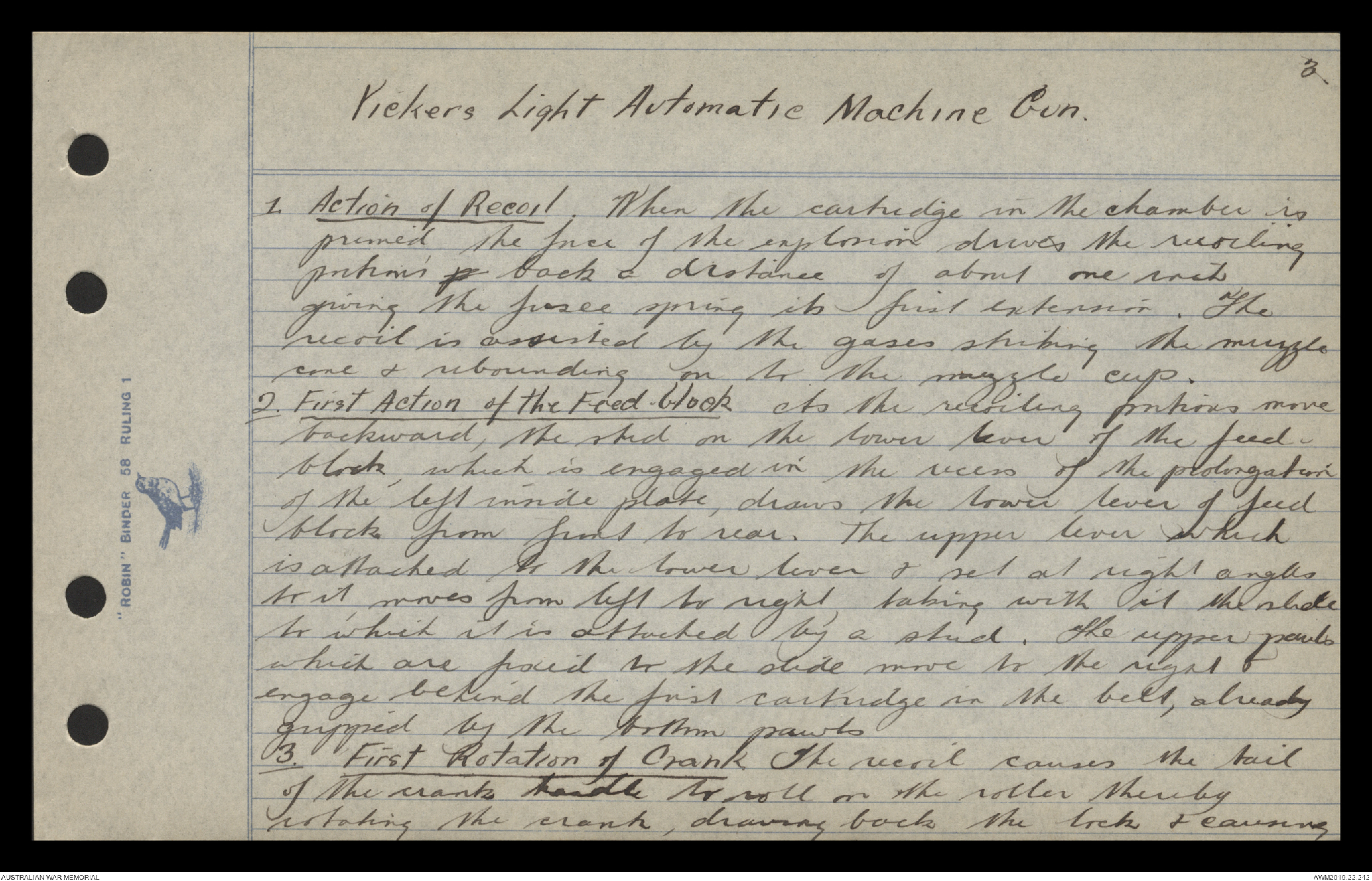
Vickers Light Automatic Machine Gun
1. Action of Recoil. When the cartridge in the chamber is
primed, the force of the explosion drives the recoiling
portions p back a distance of about one inch
giving the fusee spring its first extension. The
recoil is assisted by the gases striking the muzzle
cone & rebounding on to the muzzle cup.
2. First Action of the Feed Block As the recoiling portions move
backward, the skid on the lower lever of the feed
block, which is engaged in the recess of the prolongation
of the left inside plate, draws the lower lever of feed
block from front to rear. The upper lever which
is attached to the lower lever & set at right angles
to it, moves from left to right, taking with it the slide
to which it is attached by a stud. The upper pawls
which are fixed to the slide move to the right &
engage behind the first cartridge in the belt, already
gripped by the bottom pawls.
First Rotation of Crank The recoil causes the tail
of the crank handle to roll on the roller thereby
rotating the crank, drawing back the lock & causing
4.
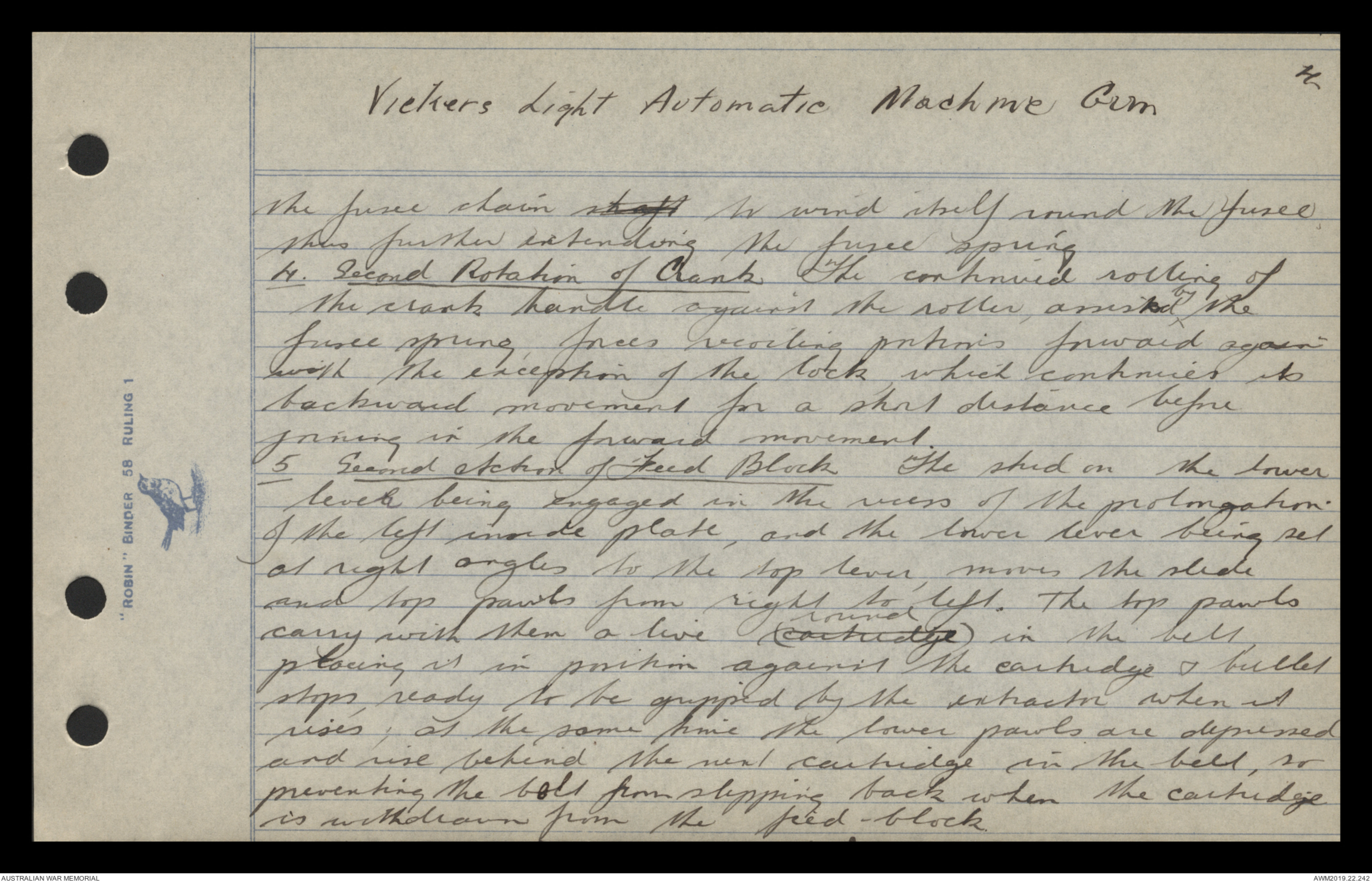
Vickers Light Automatic Machine Gun
the fusee chain shaft to wind itself round the fusee
thus further extending the fusee spring.
4. Second Rotation of Crank The continued rolling of
the crank handle against the roller, assisted ^by the
fusee spring, forces recoiling portions forward again
with the exception of the lock, which continues its
backward movement for a short distance before
joining in the forward movement.
5. Second Action of Feed Block The skid on the lower
lever being engaged in the recess of the prolongation
of the left inside plate, and the lower lever being set
at right angles to the top lever, moves the slide
and top pawls from right to left. The top pawls
carry with them a live (cartridge round) in the belt,
placing it in position against the cartridge & bullet
stops, ready to be gripped by the extractor when it
rises, at the same time the lower pawls are depressed
and rise behind the next cartridge in the belt, so
preventing the bolt from slipping back when the cartridge
is withdrawn from the feed block.
5.
Vickers Light Automatic Machine Gun
6. Outside Action of Lock When the lock comes back
a live round is taken from the feed block, the
cartridge being gripped between the upper & lower
projections of the gib, and an empty case from
the chamber. The horns of the extractor ride along
the skid cams until they are forced down by the
ramps on the underside of the rear-cover. The
live round which has been taken from the feed
block, is then opposite the chamber, and the empty
case from the chamber drops off or is ready to be ejected.
7. Cocking the Lock. The rotation of the crank
gives the side lever head & connecting rod a backward
and upward movement. The side lever head, engaging
bearing on the tail of the tumbler rotates it on its
axis and the head of the tumbler, being engaged in
the recess in the firing pin draws the firing pin to
the rear. The long arm of the lock-spring, which is
engaged behind the projection on the firing pin, is
compressed towards the short arm. The short arm
bearing in the nose of the trigger forces it over the bent
6.
Vickers Light Automatic Machine Gun
of the tumbler. The side lever head bearing still
further on the firing pin tail of the tumbler further
rotates it on its axis drawing the firing pin still
more to the rear, & further compresses the lock-spring
until the bend in the firing pin becomes engaged
with the bent on the rear, activated by the rear spring
The lock is now fully cocked.
8. Forward Rotation of Crank
When the force of the explosion is expended the action
of the fusee spring comes into play, unwinding the
fusee chain from the fusee, so rotating the crank
and causing the lock to go forward again.
9 Forward movement of lock.
When the lock goes forward, the flanges ride
along the lock guides and a live round from the
feed block is placed in the chamber. The side
levers bearing bearing on the extractor levers, cause
the extractor to rise. When the extractor rises,
the upper projector on the gib rides over the base
of the cartridge in the chamber feed-block, the
 Transcriber 6897
This transcription item is now locked to you for editing. To release the lock either Save your changes or Cancel.
This lock will be automatically released after 60 minutes of inactivity.