Service notebook of Harold Gordon Cornell - 1917 - Part 14
Rigging (Wires & Their Functions)
Stagger Wires - Wires running diagonally between the
front & rear interplane struts. These wires maintain
stagger
Distance Wires - a wire connecting the top & bottom
ailerons & preserves the gap.
Compensating Wire - a wire connecting the right
hand top aileron with the left hand top
aileron starting from king post on the right
around a pulley on the front spar around
another pulley & then connecting to a king post
on the left top aileron.
Diagram - see original document
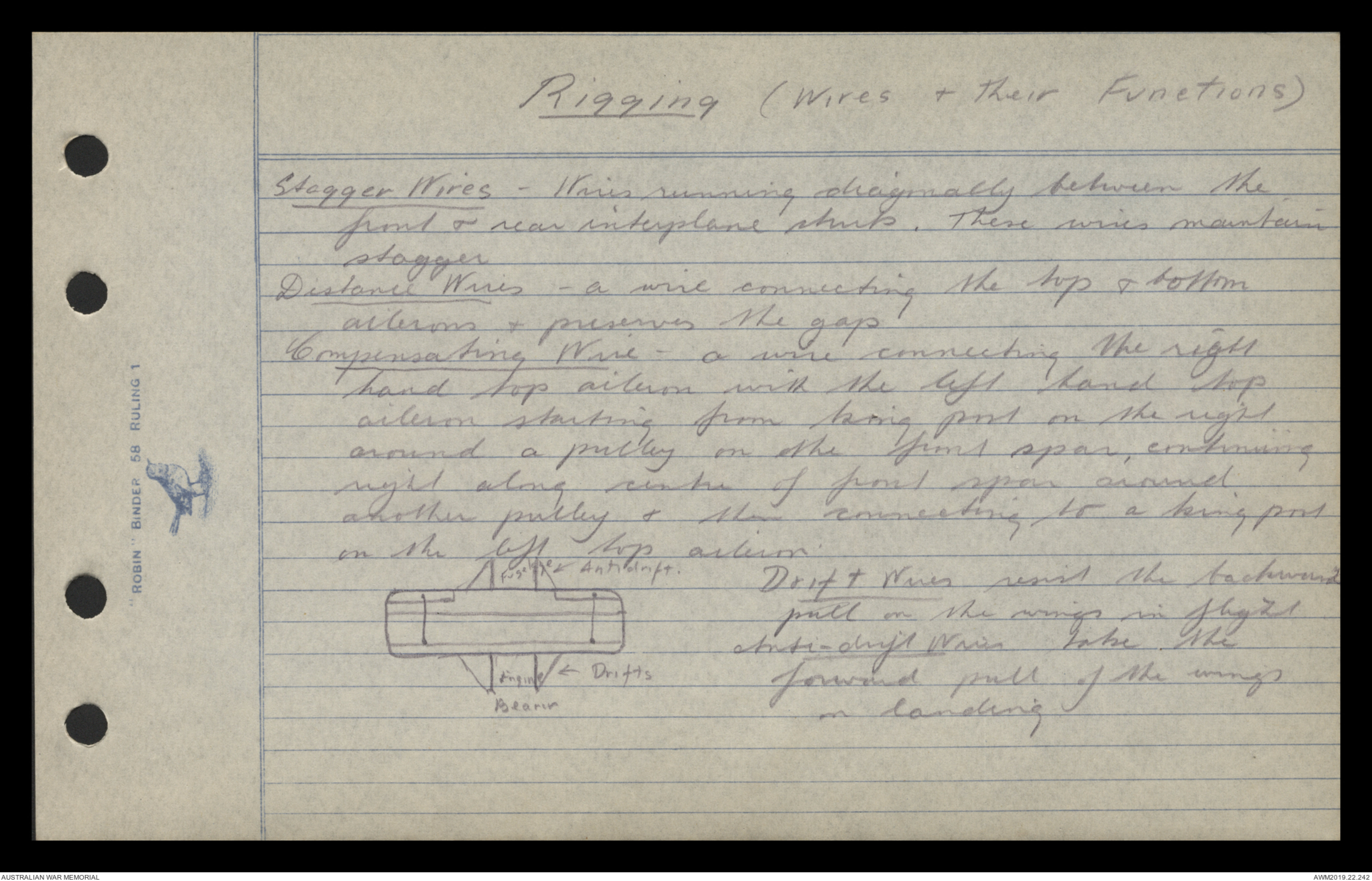
Fuselage Antidrift.
Engine Drifts
Bearer
Drift Wires resist the backward
pull on the wings in flight
Anti-drift Wires take the
forward pull of the wings
on landing
1.
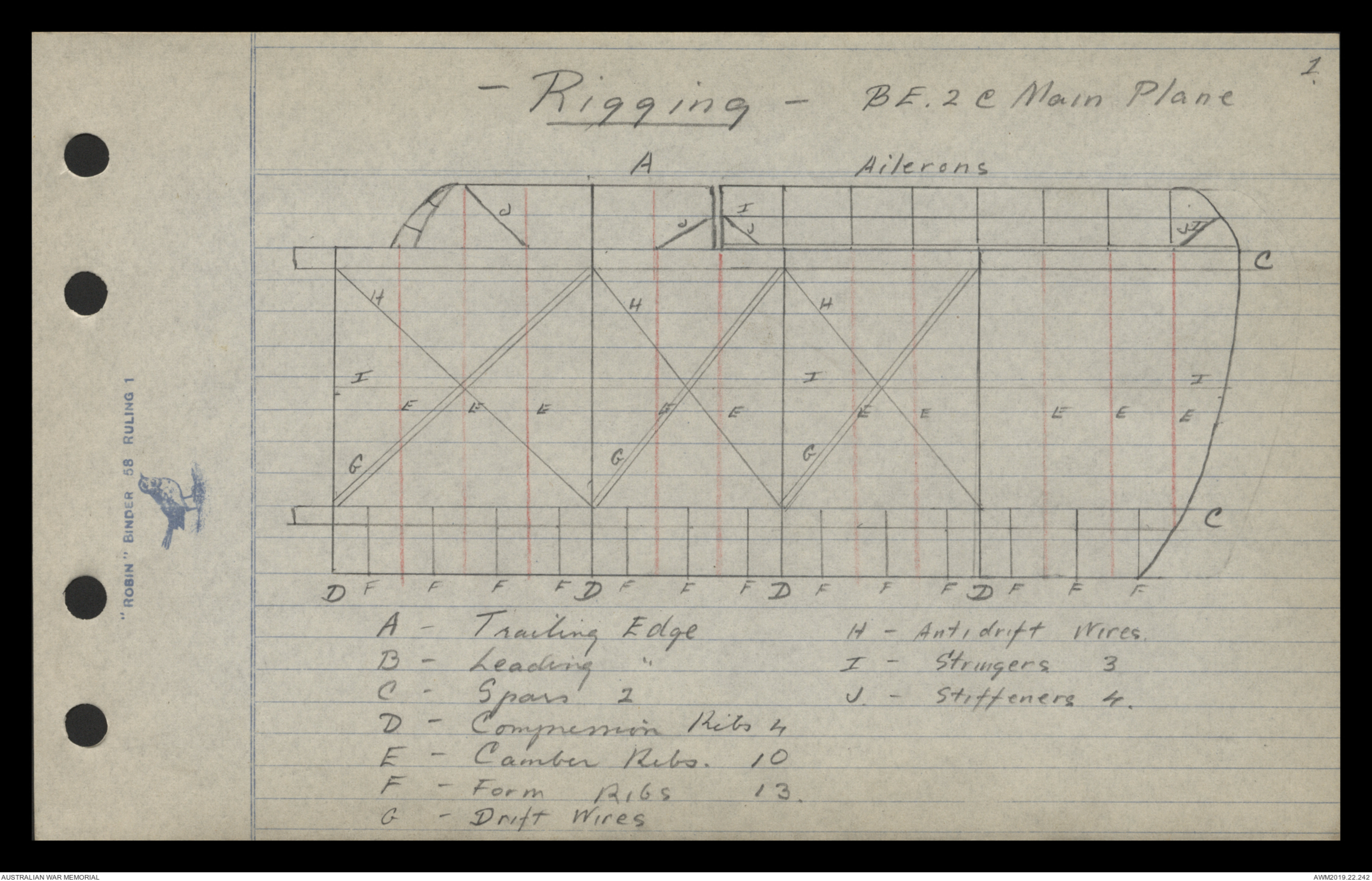
- Rigging - BE. 2C Main Plane
Ailerons
Diagram - see original document
A - Trailing Edge H - Antidrift Wires
B - Leading " I - Stringers 3
C - Spars 2 J - Stifferers 4.
D - Compression Ribs 4
E - Camber Ribs 10
F - Form Ribs 13.
G - Drift Wires
2
Rigging -BE 2c Main Plane.
Leading Edge, made of Spruce, Trailing Edge - Ash
Spars are main transverse members of the plane: made
of spruce.
Compression Rib acts as an ordinary rib besides
bearing the stress of compression produced by the
tension of the drift & antidrift wires.(Spruce)
Camber Ribs are light skeleton ribs which chiefly
serve to give shape to the plane ; spruce flanges,
3 Ply ash, webbing,
Form Rib A small rib which improves the camber
between the leading edge & the front spar (Spruce)
Stringers Keep the ribs at the proper distance apart
also prevents them from twisting Spruce.
Stiffeners A diagonal piece of wood which strengthens
the wing tip or any corner. (spruce or ash)
Propeller Torque The tendency of a prop. to turn
a machine over sideways in a direction opposite
to that in which it revolves.
Wash-in when the angle of incidence is increased
towards the wing tip.
(3)
Rigging :- BE 2c Main Plane.
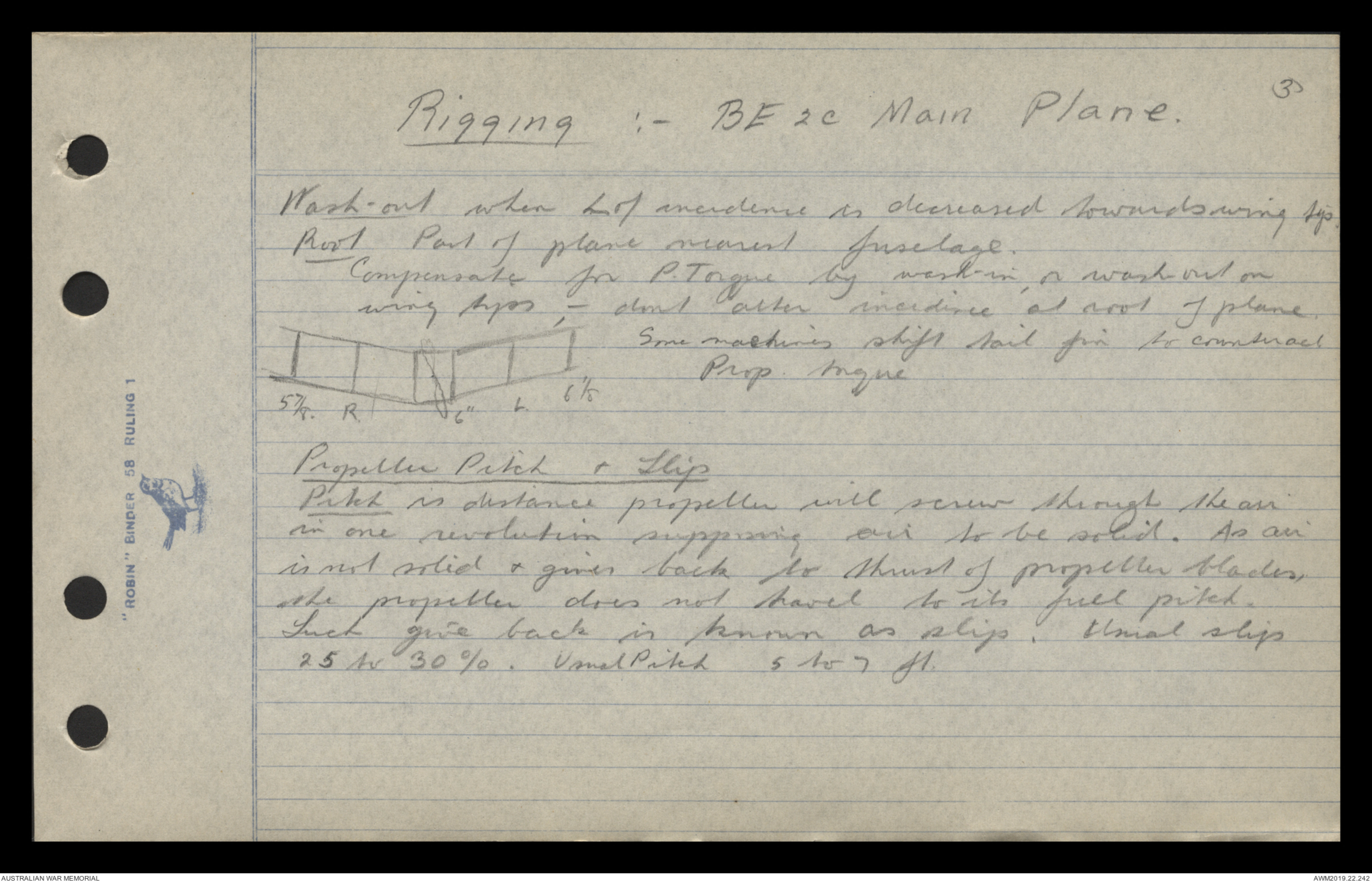
Wash-out when l of incidence is decreased towards wing tip.
Root Part of plane nearest fuselage.
Compensates for P. Torque by wash-in, or wash-out on
wing tips, - dont alter incidence at root of plane.
Diagram - see original document
Some machines shift tail fin to counteract
Prop torque
Propeller Pitch & Slip
Pitch is distance propeller will screw through the air
in one revolution supposing air to be solid. As air
is not solid & gives back to thrust of propeller blades
the propeller does not travel to its full pitch.
Such give back is known as slip. Usual slip
25 Av 30%. Usual Pitch 5 to 7 ft.
1
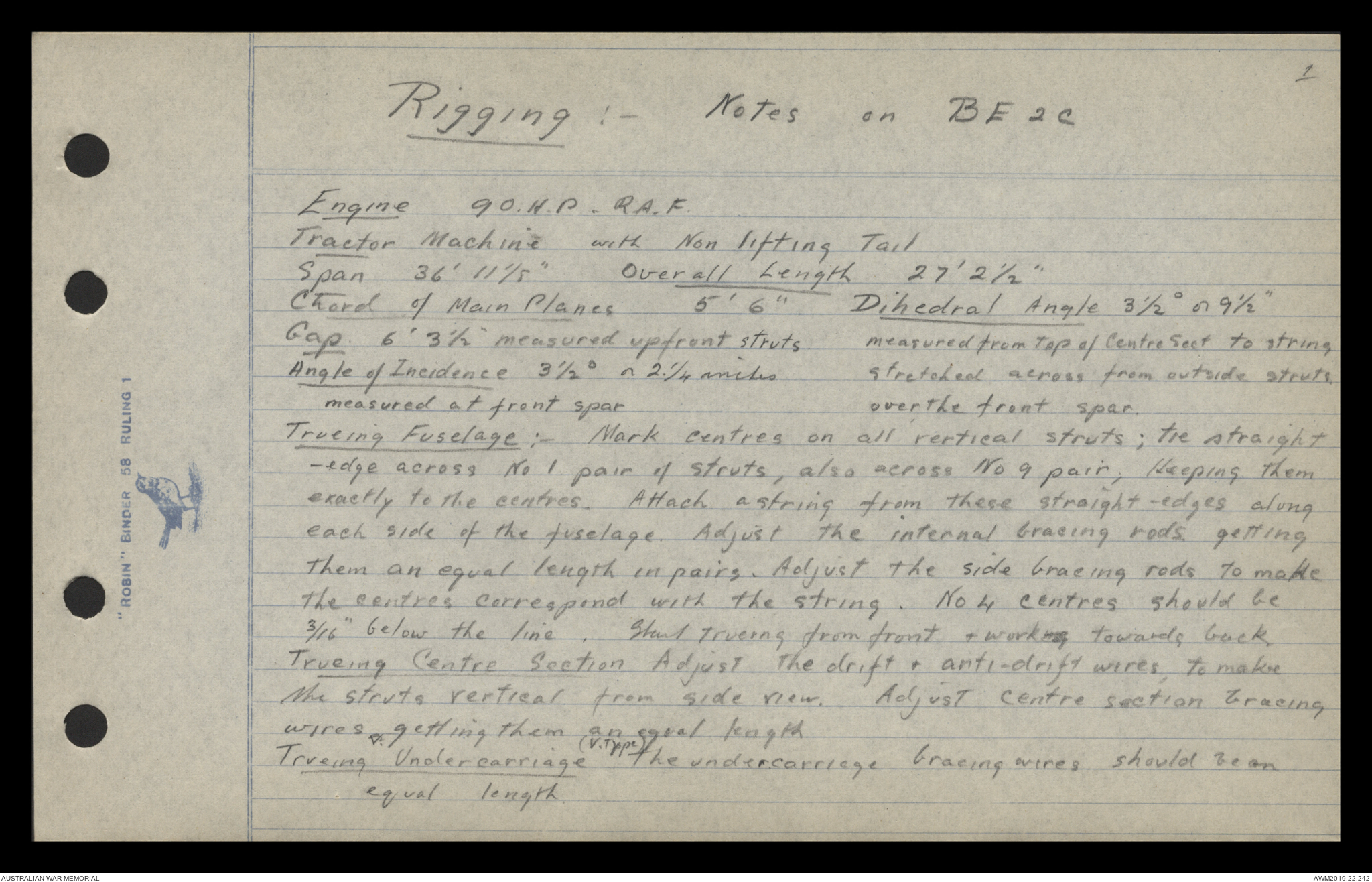
Rigging :- Notes on BE 2c
Engine 90 H.P. R.A.F.
Tractor Machine with Non lifting Tail
Span 36' 11 1/8" Overall Length 27' 2½"
Chord of Main Planes 5'6"
Dihedral Angle 3½o or 9½"
measured from Top of Centre Sect to string
stretched across from outside struts
over the front spar
Gap 6' 3½" measured upfront struts
Angle of Incidence 3½o or 2¼ inches
measured at front spar
Trueing Fuselage :- Mark centres on all vertical struts; the straight-edge
across No 1 pair of struts also across No 9 pair, Keeping them
exactly to the centres. Attach a string from these straight-edges along
each side of the fuselage. Adjust the internal bracing rods getting
them an equal length in pairs. Adjust the side bracing rods to make
the centres correspond with the string. No 4 centres should be
3/16" below the line. Start trueing from front & working towards back
Trueing Centre Section Adjust the drift & anti-drift wires, to make
the struts vertical from side view. Adjust centre section bracing
wires getting them an equal length
Trueing Undercarriage (V.Type) The undercarriage bracing wires should be
an equal length.
2
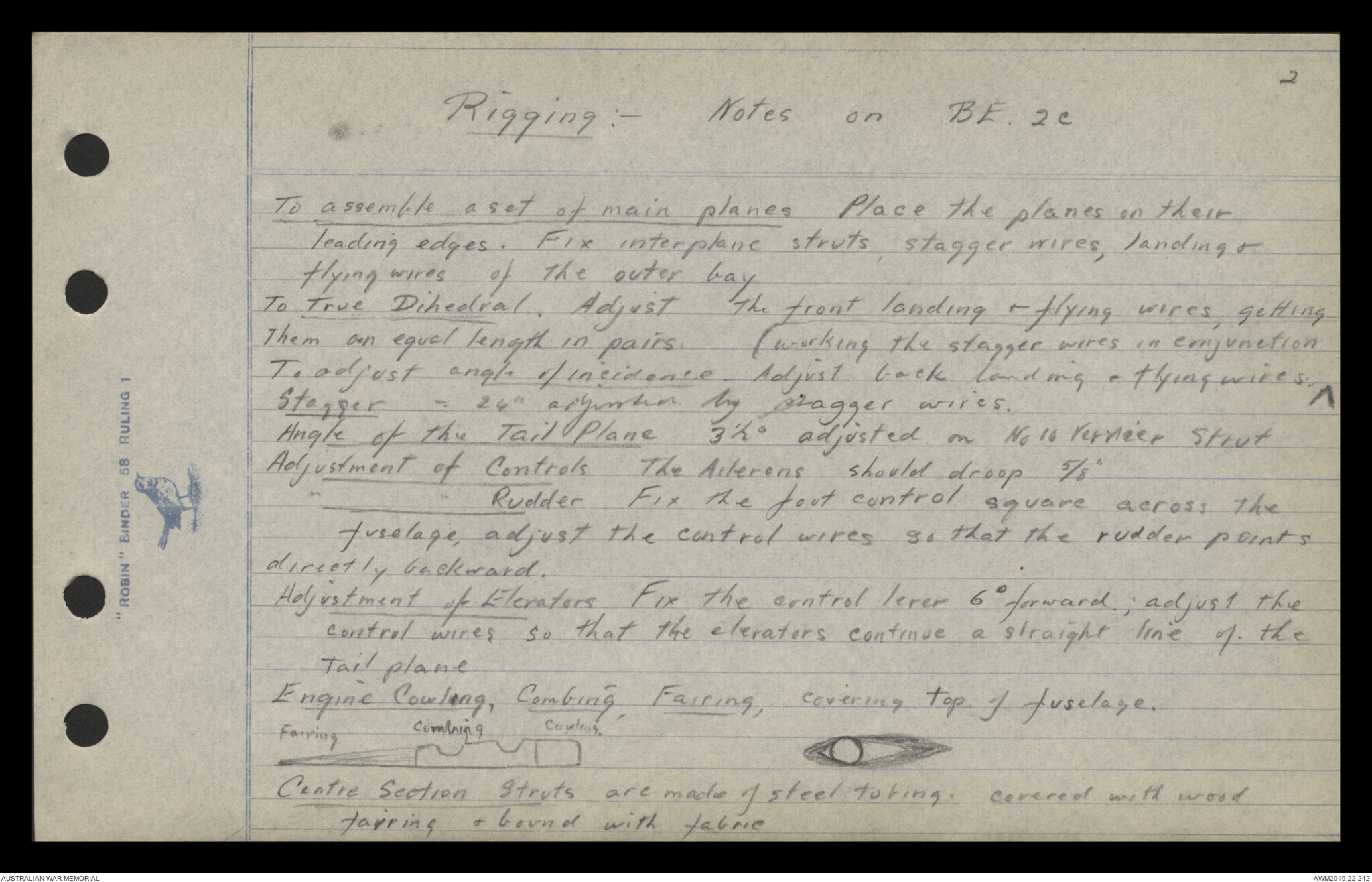
Rigging:- Notes on BE . 2c
To assemble a set of main planes Place the planes on their
leading edges. Fix interplane struts, stagger wires, landing &
flying wires of the outer bay
To True Dihedral. Adjust the front landing & flying wires, getting
them an equal length in pairs. (working the stagger wires in conjunction
To adjust angle of incidence. Adjust back landing & flying wires, ∧
Stagger - 24" adjusted by stagger wires.
Angle of the Tail Plane 3½o on No 10 Vernier Strut
Adjustment of Controls The Ailerons should droop 5/8"
' " Rudder Fix the foot control square across the
fuselage, adjust the control wires so that the rudder points
directly backward.
Adjustment of Elevators Fix the central lever 6o forward; adjust the
control wires so that the elevators continue a straight line of the
tail plane
Engine Cowling, Combing, Fairing, covering top of fuselage.
Diagram - see original document.
Centre Section Struts are made of steel tubing. covered with wood
fairing & bound with fabric
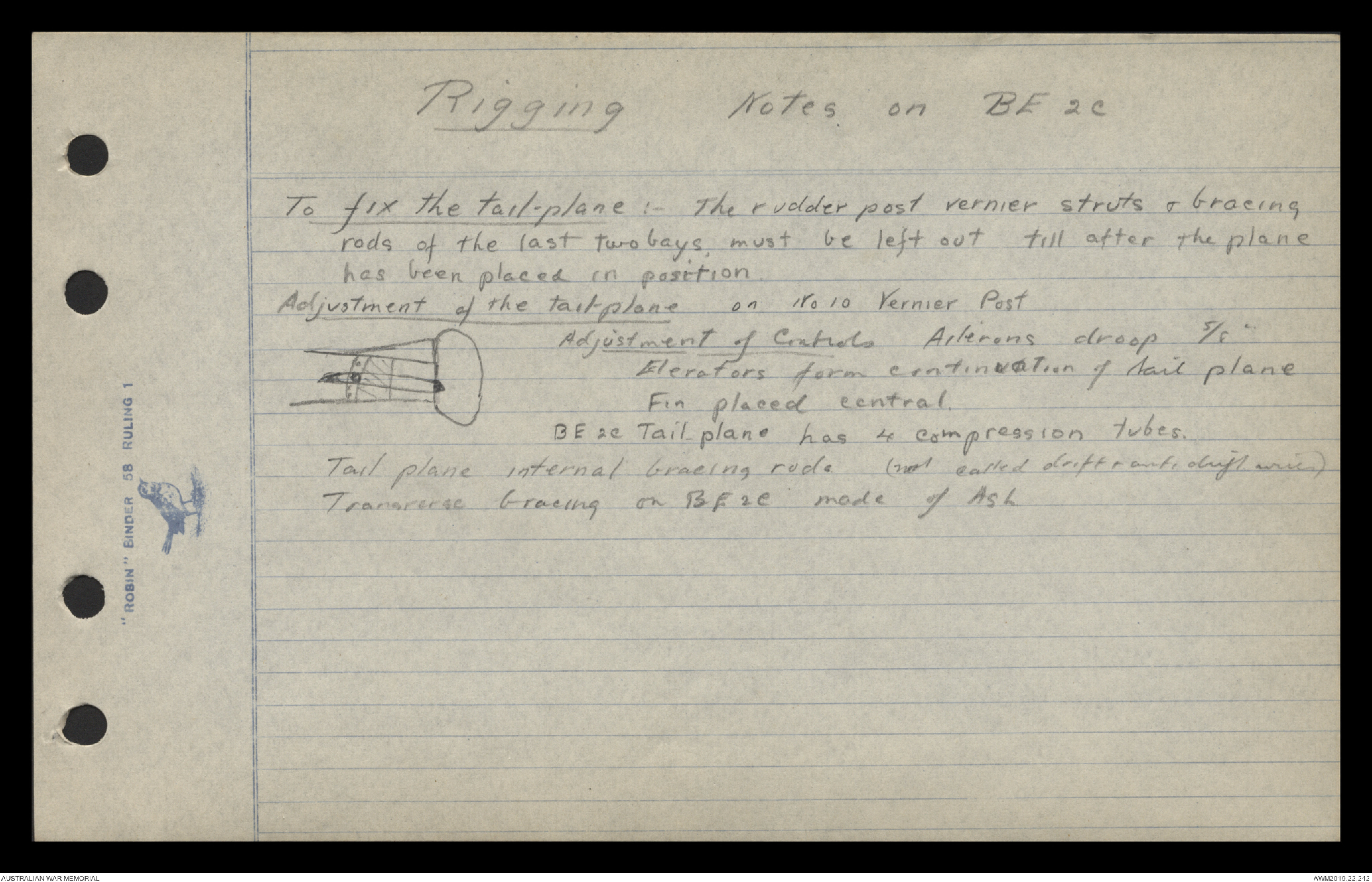
Rigging:- Notes on BE . 2c
To fix the tail-plane : - The rudder post vernier struts & bracing
rods of the last two bays must be left out till after the plane
has been placed in position
Adjustment of the tail-plane on No 10 Vernier Post
diagram - see original document
Adjustment of Controls Ailerons droop 5/8 "
Elevators form continuation of tail plane
Fin placed central.
BE 2c Tail plane has 4 compression tubes.
Tail plane internal bracing rod (not called drift & anti drift wires)
Transverse bracing on BE 2C made of Ash
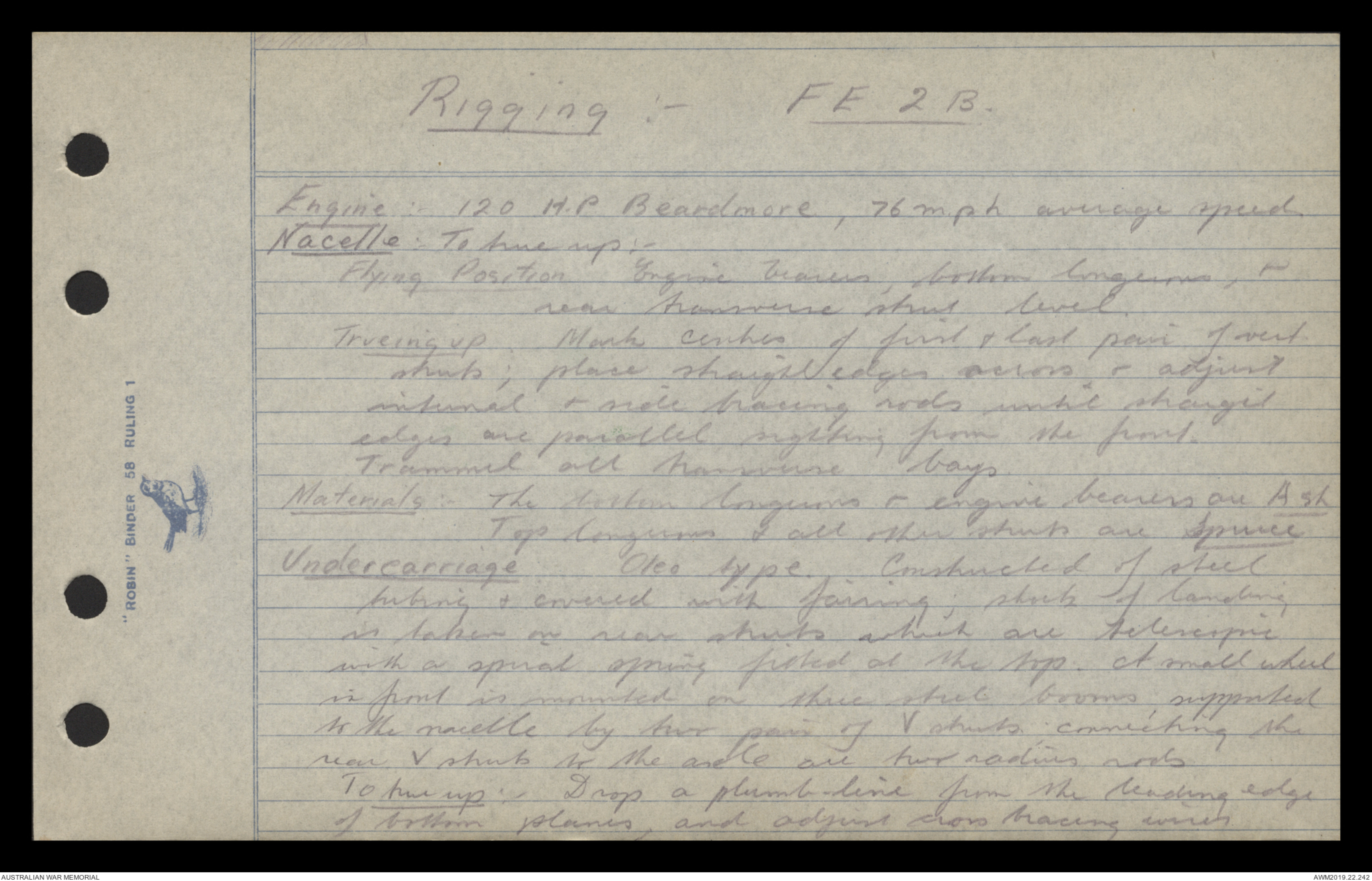
Rigging:- FE 2 B.
Engine :- H.P. Beardmore, 76 mph average speed
Nacelle : - To tune up :-
Flying Position Engine bearers, bottom longeron, &
rear transverse strut level.
Trueing up Mark centres of first & last pair of vent
struts; place straight edges across & adjust
internal & side bracing rods until straight
edges are parallel sighting from the front.
Trammel all transverse bays.
Materials :- The bottom longerons & engine bearers are Ash
Top longerons & all other struts are Spruce
Undercarriage Oleo type, Constructed of steel
tubing & covered with fairing; shock of landing
is taken on rear struts which are telescopic
with a spiral spring fitted at the top. A small wheel
in front is mounted on three steel booms, supported
to the nacelle by two pair of V struts connecting the
rear v struts to the axle are two radius rods
to tune up : - Drop a plumb line from the leading edge
of bottom planes, and adjust cross bracing wires
Rigging:- FE 2 B.
until the centre of axle is 2 7/8" behind plumb-line
Centre Section : - Assembling : - Place top plane on leading edge
on ground; fit struts (8) ; lift up & bolt the 4 centre
struts to top longeron of nacelle, attaching cross- bracing,
drift & anti-drift wires, to hold in position.
Fit the two lower sections & wire up.
To true up :- Just trammel cross bracing wires & adjust
front landing & flying wires until leading edge of top
plane is straight. Adjust rear landing & flying wires
for incidence. Stagger is nil.
Main Planes : - Dihedral 4° or 10.85" measured at each
end of centre section. The angle of incidence is 4° 9',
or 2 ¼". Stagger is nil. Hilium drop 5/8"
- FE 2 B. -
Tail Section :- Assembling Outrigger
Lay the top & bottom booms on one side on ground;
(top boom longer) fit struts & ride bracing wires.
Do same with other side; lift both sides upright; &
fit transverse struts transverse & internal bracing wire
The skid is fitted to the lower rear transverse strut.
Next fit rudder post & rudder (Rudder post is double the inner
tube acting as a strut the outer tube, to which rudder
is mounted, runs on ball bearings on the inner tube)
Lift outrigger up & bolt the centre section.
To tie up. outrigger. First trammel the internal bays,
adjust side bracing wires, making lower booms. level &
straight in flying position; side struts vertical; top
booms straight.
Tail plane non lifting, stream line section,
(lifting tail is either flat or cambered) is fitted to top of
top boom, the front span pivoted the rear spar fixed to
a vernier scale, on which adjustments are made.
To tie tail plane Adjust on vernier scale until the
distance between the under side of rear span of & top
 Sam scott
This transcription item is now locked to you for editing. To release the lock either Save your changes or Cancel.
This lock will be automatically released after 60 minutes of inactivity.