Service notebook of Harold Gordon Cornell - 1917 - Part 13
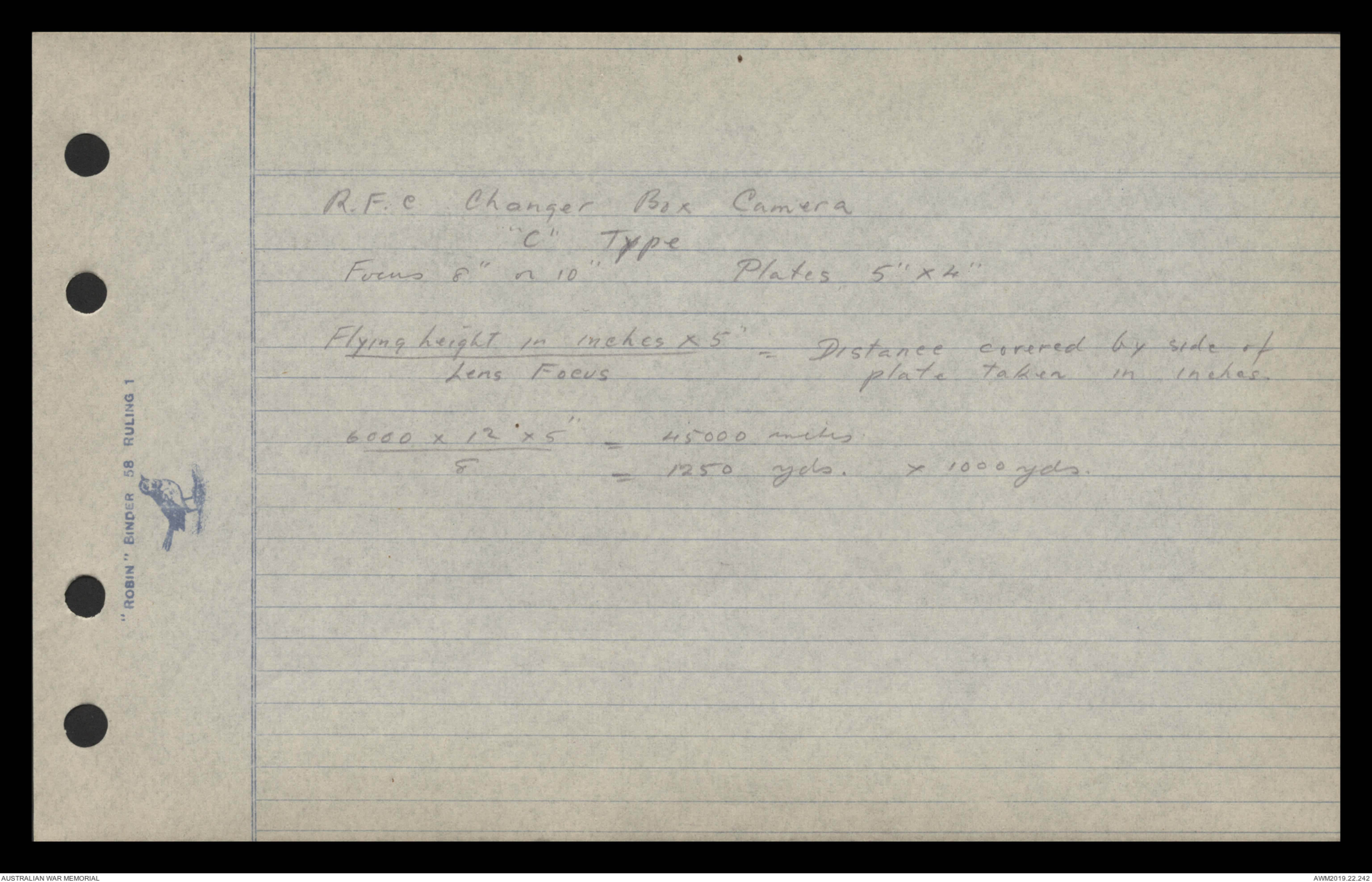
R.F.C Changer Box Camera
"C" Type
Focus 8" or 10" Plates 5" x 4"
Flying height in inches x 5" = Distance covered by side of
Lens Focus plate taken in inches.
6000 x 12 x 5” = 45000 inches
8 = 1250 yds. x 1000 yds.
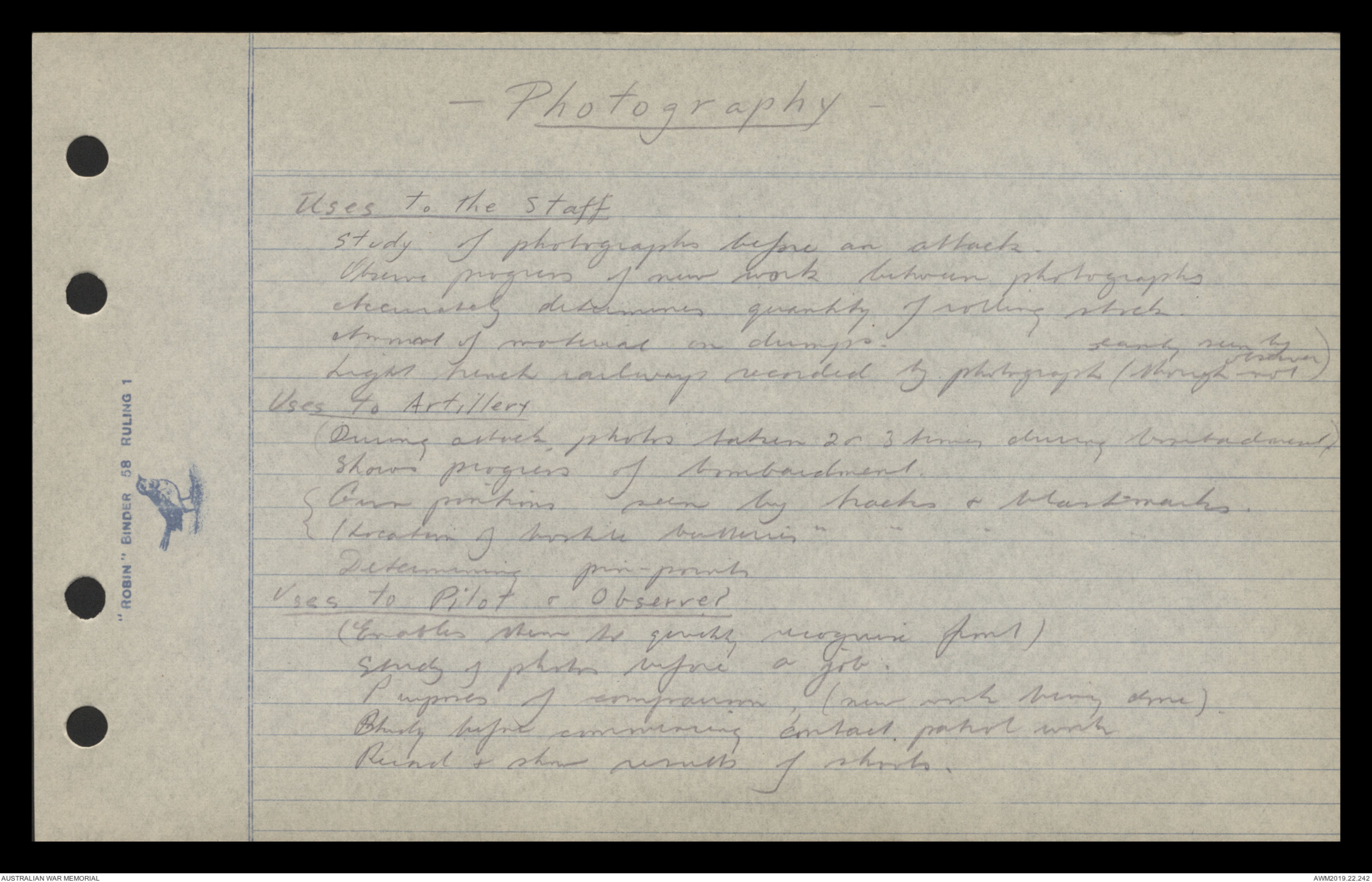
— Photography —
Uses to the Staff
Study of photographs before an attack.
Observe progress of new work between photographs
Accurately determines quantity of rolling stock.
Amount of material in dumps.
Light trench railways recorded by photograph (though not easily seen by observer)
Uses to Artillery
(During attack, photos taken 2 or 3 times during bombardment)
shows progress of bombardment.
(Gun positions seen by tracks & blast marks.
(/ Location of hostile batteries ” ” ” ”
Determining pin-points
Uses to Pilot & Observer
(Enables them to quickly recognise front)
Study of photos before a job.
Purposes of comparison, (new work being done).
Study before commencing contact, patrol work
Record & show results of shoots.
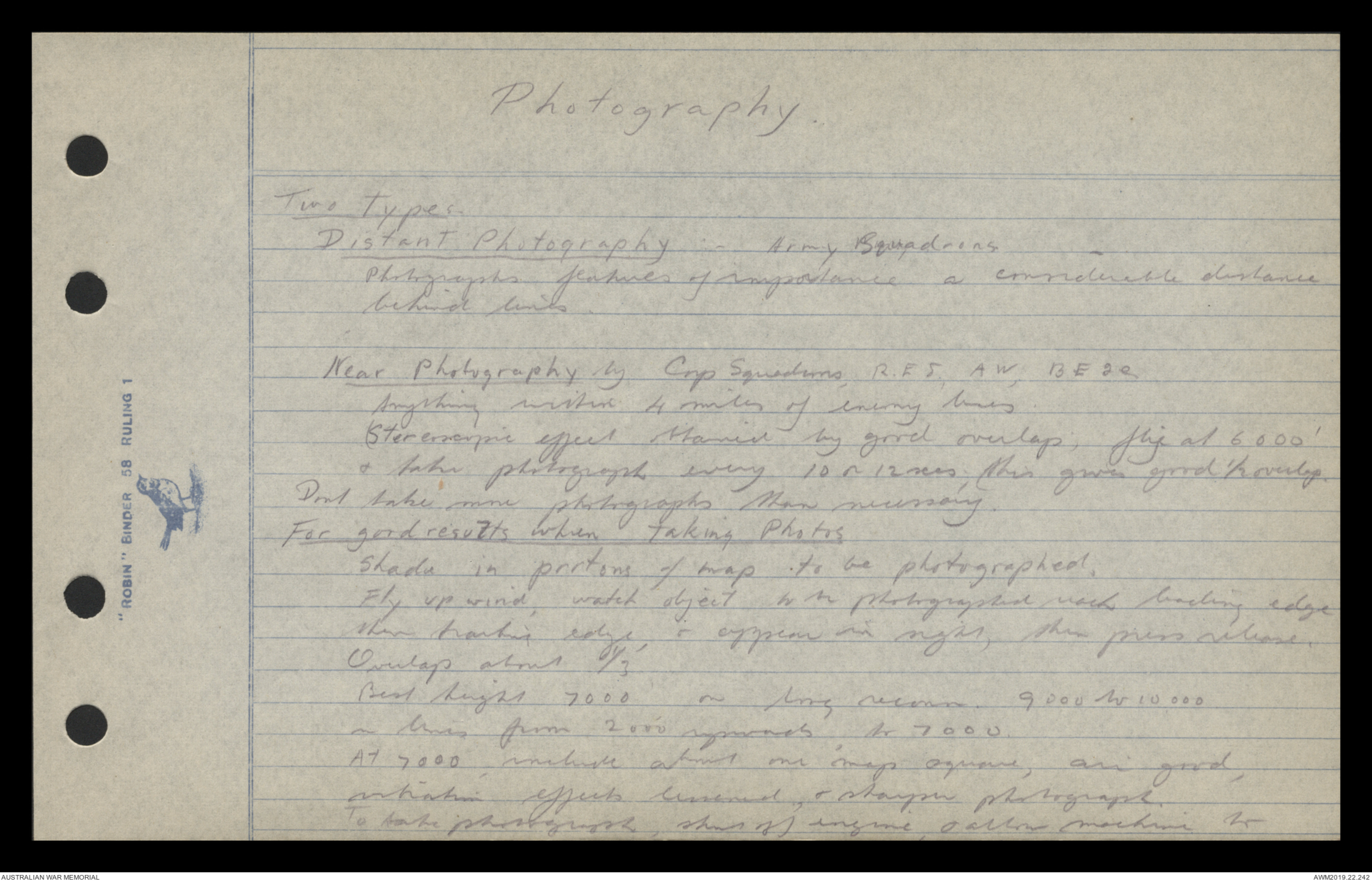
Photography.
Two Types.
Distant Photography :- Army Squadrons
Photographs features of importance a considerable distance
behind lines.
Near Photography by Corp Squadrons, R.E 5, AW, BE 2e.
Anything within 4 miles of enemy lines.
(Stereoscopic effect obtained by good overlap; fly at 6000’
& take photograph every 10 or 12 secs, this gives good ½ overlap.
Don’t take more photographs than necessary.
For good results when taking Photos
Shade in portions of map to be photographed.
Fly up wind, watch object to be photographed reach leading edge
then trailing edge, & appear in sight, then press release.
Overlap about 1/3
Best height 7000 on long reconn. 9000 to 10,000
on lines from 2000 upwards to 7000.
At 7000, include about one map square, air good,
vibration effects lessened, & sharpen photograph.
To take photograph, shut off engine, & allow machine to
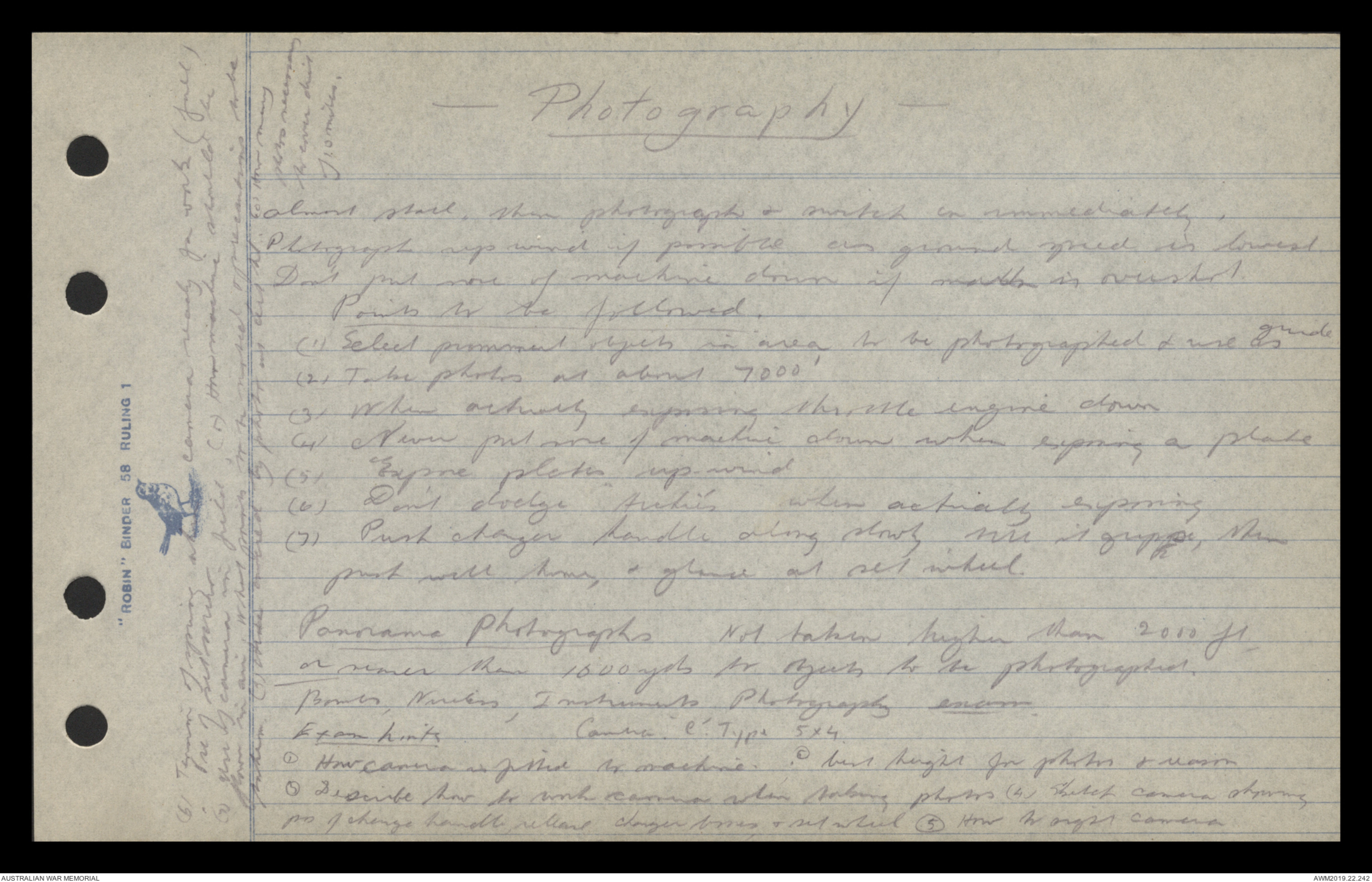
— Photography —
almost stall, then photograph & switch on immediately,
Photograph up wind if possible as ground speed is lowest.
Don't put nose of machine down if matter is overshot.
Points to be followed.
(1) Select prominent objects in area to be photographed & use as guide
(2) Take photos at about 7000'
(3) When actually exposing throttle engine down
(4) Never put nose of machine down when exposing a plate
(5) Expose plates up-wind
(6) Don't dodge "Hickies' when actively exposing
(7) Push charger handle along slowly till it grips, then
push well home, & glance at set wheel.
Panorama Photographs Not taken higher than 2000 ft
or nearer than 1600 yds for objects to be photographed.
Bombs, Wireless, Instruments, Photography exam.
Exam hints Camera e'. Type 5x4.
(1) How camera is fitted to machine. (2) best height for photos & reason
(3) Describe how to work camera when taking photos (4) Sketch camera showing
pos of charge handle, release charger boxes, & set wheel (5) How to sight camera
(6) Tension of spring when camera ready for work (full)
Use of set mirror.
(7) Use of camera in field (8) How machine should be
flown in air. What points to be noted & precautions to be
taken (9) Area covered by photo is [[distant?]] (10) How many
secs necessary
to cover dist
of 10 miles.
1
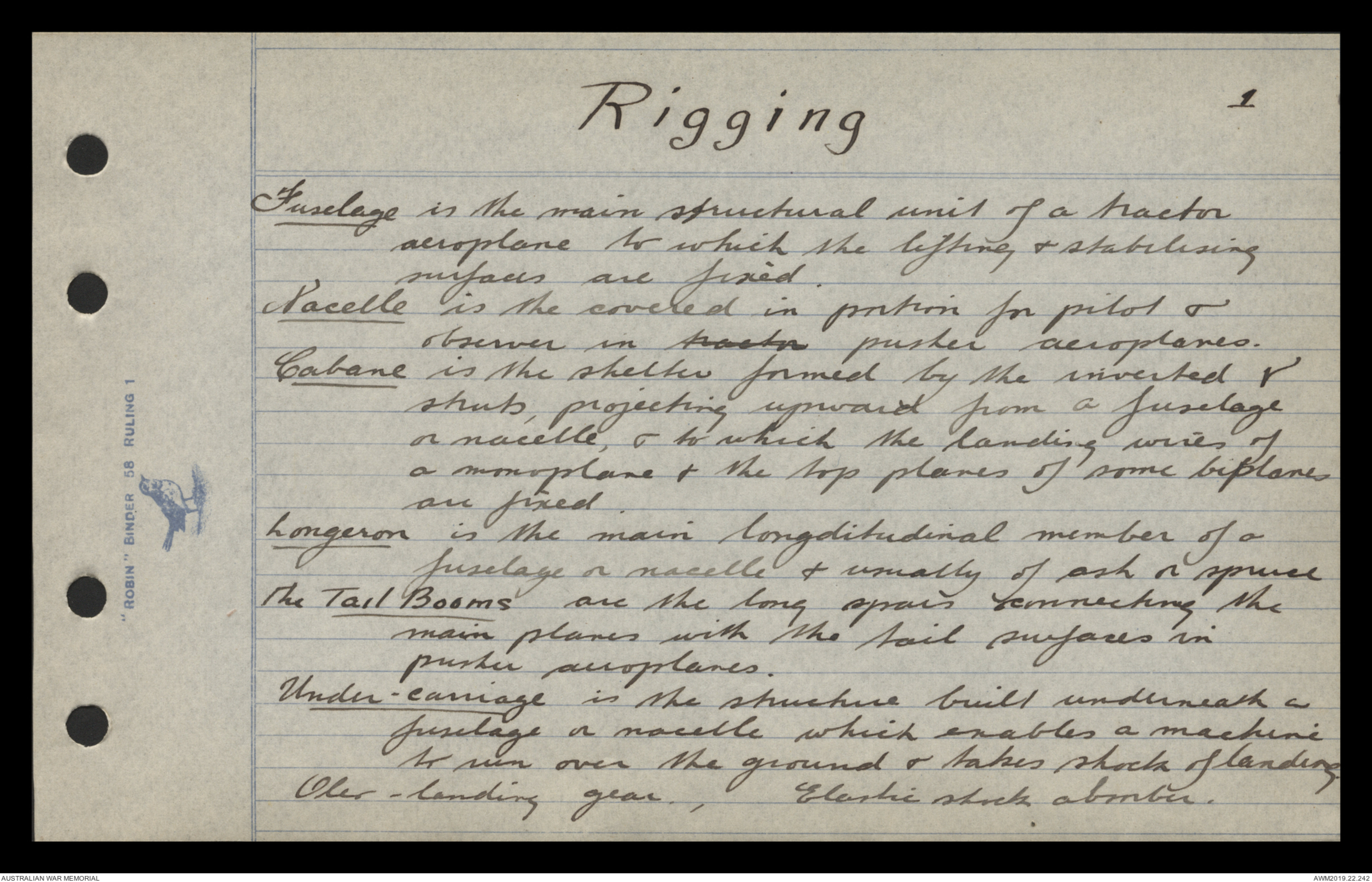
Rigging
Fuselage is the main structural unit of a tractor
aeroplane to which the lifting & stablilising
surfaces are fixed.
Nacelle is the covered in portion for pilot &
observer in tractor pusher aeroplanes.
Cabane is the shelter formed by the inverted V
struts, projecting upward from a fuselage
or nacelle, & to which the landing wires of
a monoplane & the top planes of some biplanes
are fixed.
Longeron is the main longditudinal member of a
fuselage or nacelle & usually of ash or spruce
The Tail Booms are the long spars connecting the
main planes with the tail surfaces in
pusher aeroplanes.
Under-carriage is the structure built underneath a
fuselage or nacelle which enables a machine
to run over the ground & takes shock of landing
Oher-landing gear, Elastic shock absorber.
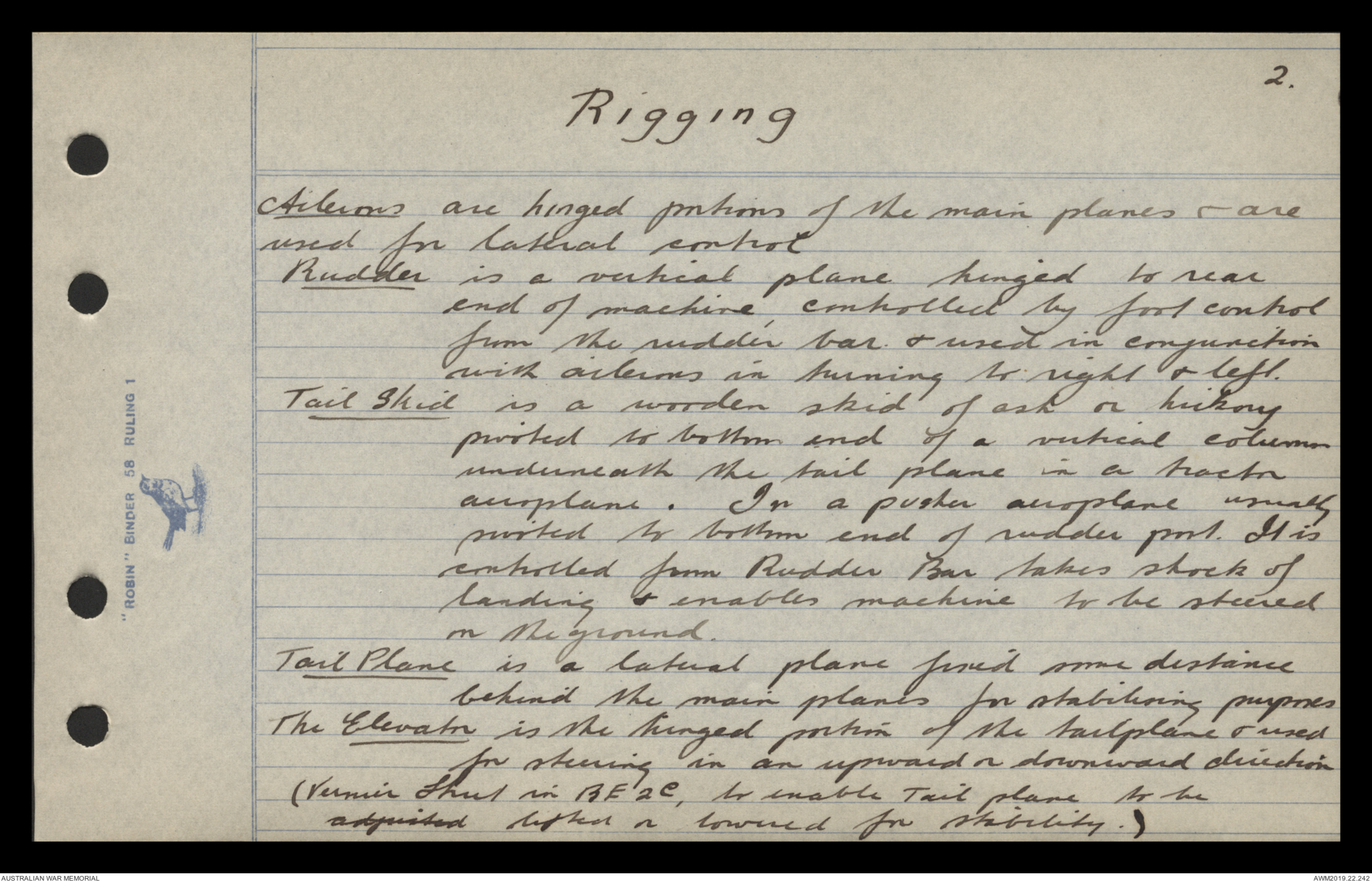
2.
Rigging
Ailerons are hinged portions of the main planes & are
used for lateral control
Rudder is a vertical plane hinged to rear
end of machine, controlled by foot control
from the rudder bar. & used in conjunction
with ailerons in turning to right & left.
Tail Skid is a wooden skid of a vertical column
underneath the tail plane in a tractor
aeroplane. In a pusher aeroplane usually
pushed to bottom end of rudder post. It is
controlled from Rudder Bar takes shock of
landing & enables machine to be steered
on the ground.
Tail Plane is a lateral plane fixed some distance
behind the main planes for stabilising purposes
The Elevator is the hinged portion of the tailplane & used
for steering in an upward or downward direction
(Vernier Strut in BE 2e, to enable Tail plane to beadjusted lifted or lowered for stability.)
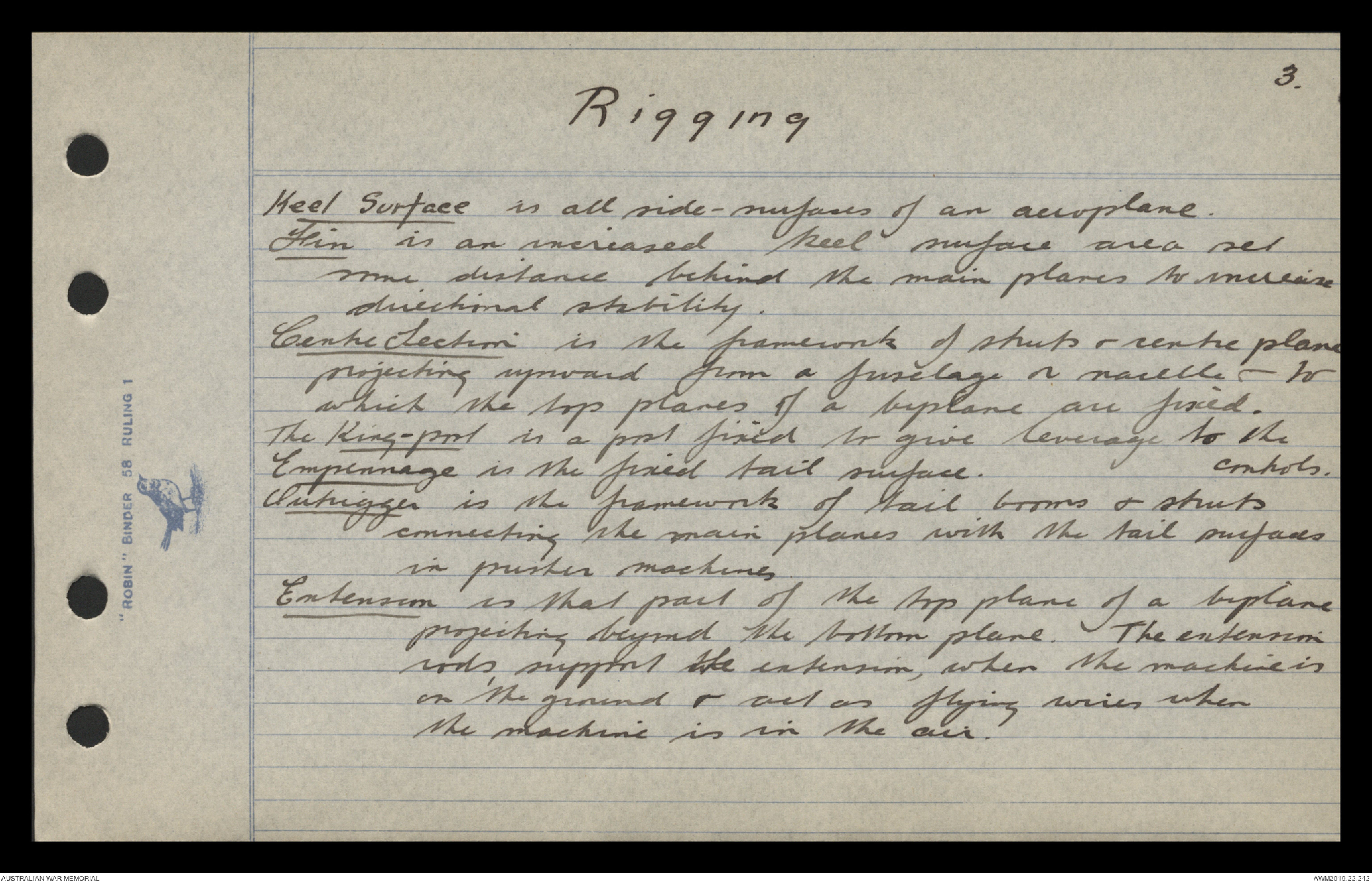
3.
Rigging
Keel Surface is all side-surfaces of an aeroplane.
Fin is an increased keel surface area set
some distance behind the main planes to increase
directional stability.
Centre Section is the framework of struts & centre plane
projecting upward from a fuselage or nacelle - to
which the top planes of a biplane are fixed.
The King-post is a post fixed to give leverage to the controls.
Empennage is the fixed tail surface.
Outrigger is the framework of tail booms & struts
connecting the main planes with the tail surfaces
in pusher machines
Extension is that part of the top plane of a biplane
projecting beyond the bottom plane. The extension
rods, support the extension, when the machine is
on the ground & act as flying wires when
the machine is in the air.
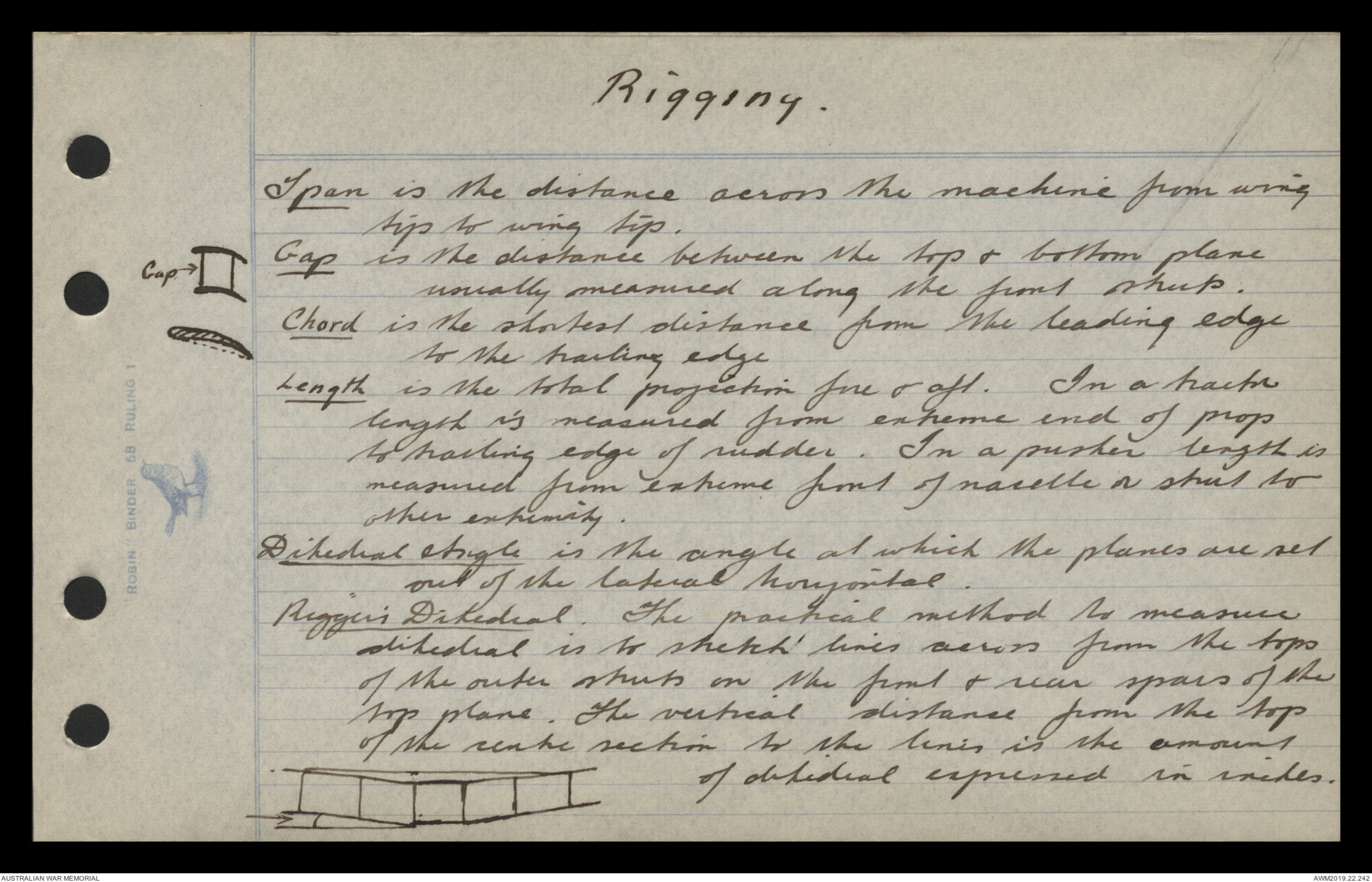
Rigging.
Span is the distance across the machine from wing
tip to wing tip.
Gap is the distance between the top & bottom plane
usually measured along the front struts.
[*Diagram - see original document*]
Chord is the shortest distance from the leading edge
to the trailing edge
[*Diagram - see original document*]
Length is the total projection fore & aft. In a tractor
length is measured from extreme end of prop
to trailing edge of rudder. In a pusher length is
measured from extreme front of nacelle or strut to
other extremity.
Dihedral Angle is the angle at which the planes are set
out of the lateral horizontal.
Rigger's Dihedral. The practical method to measure
dihedral is to stretch lines across from the tops
of the outer struts on the front & rear spars of the
top plane. The vertical distance from the top
of the centre section to the lines is the amount
of dihedral expressed in inches.
Diagram - see original document
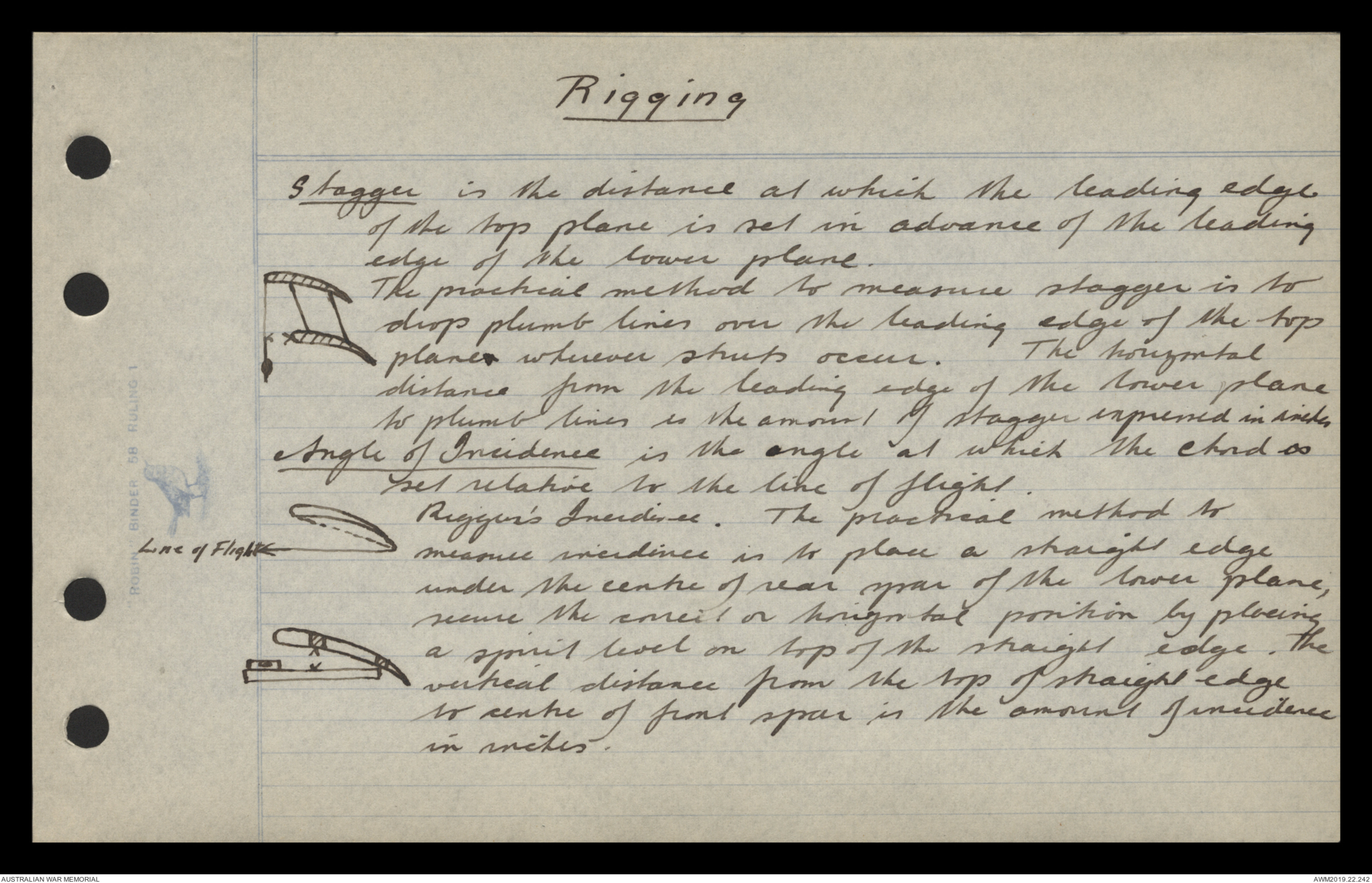
Rigging
Stagger is the distance at which the leading edge
of the top plane is set in advance of the leading
edge of the lower plane.
Diagram - see original document
The practical method to measure stagger is to
drop plumb lines over the leading edge of the top
planex wherever struts occur. The horizontal
distance from the leading edge of the lower plane
to plumb lines is the amount of stagger expressed in inches
Angle of Incidence is the angle at which the chord is
set relative to the line of flight.
Diagram - see original document
Rigger's Incidence. The practical method to
measure incidence is to place a straight edge
under the centre of rear spar of the lower plane,
secure the correct or horizontal position by placing
a spirit level on top of the straight edge. The
Diagram - see original document
vertical distance from the top of straight edge
to centre of front spar is the amount of incidence
in inches.
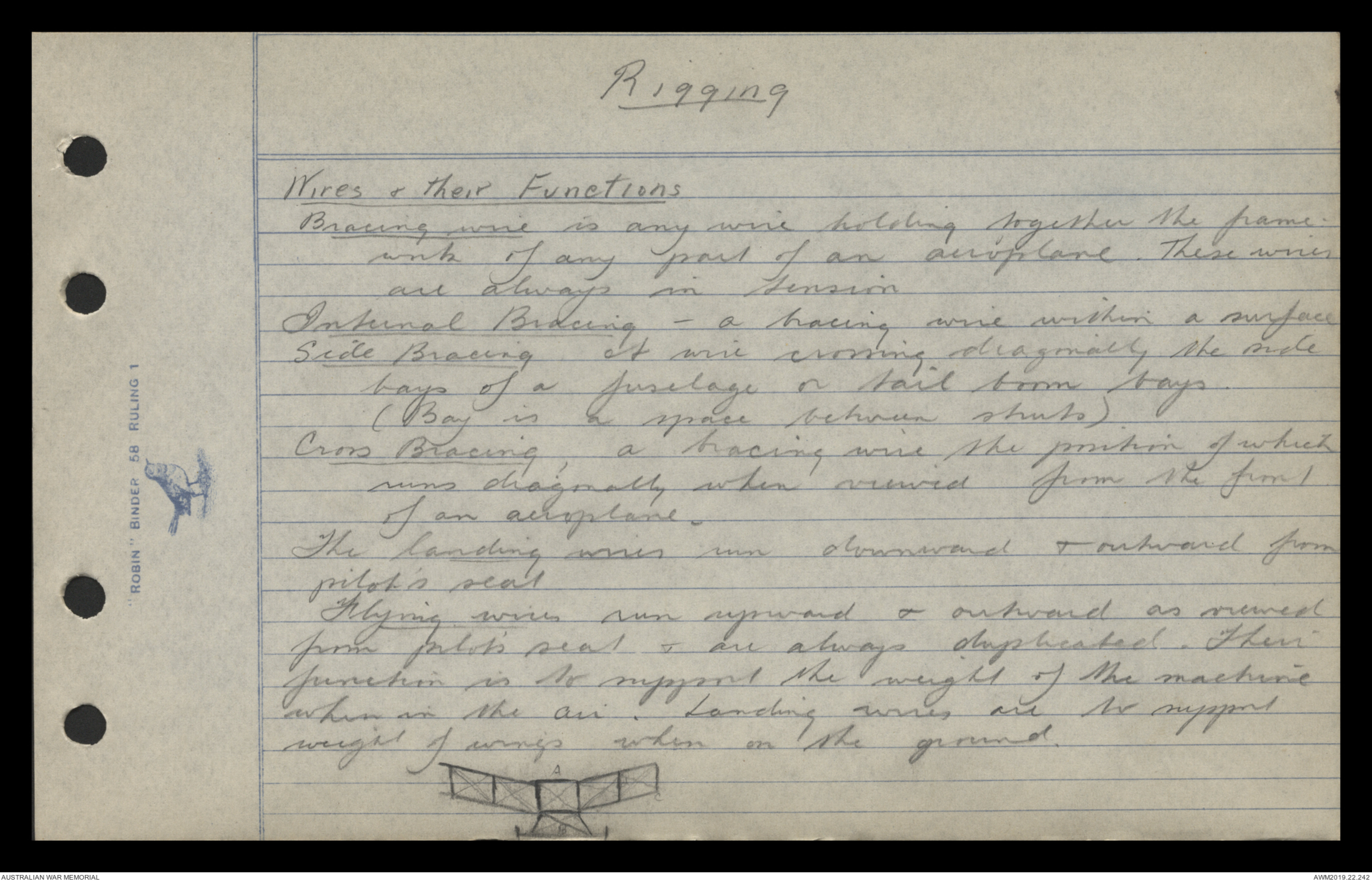
Rigging
Wires & their Functions
Bracing wire is any wire holding together the framework
of any part of an aeroplane. These wires
are always in tension
Internal Bracing - a bracing wire within a surface
Side Bracing A wire crossing diagonally the side
bays of a fuselage or tail boom bays.
(Bay is a space between struts).
Cross Bracing, a bracing wire the position of which
runs diagonally when viewed from the front
of an aeroplane.
The landing wires run downward & outward from
pilot's seat
Flying wires run upward & outward as viewed
from pilot's seat & are always duplicated. Their
function is to support the weight of the machine
when in the air. Landing wires are to support
weight of wings when on the ground.
Diagram - see original document
 Jen
Jen This transcription item is now locked to you for editing. To release the lock either Save your changes or Cancel.
This lock will be automatically released after 60 minutes of inactivity.