Service notebook of Harold Gordon Cornell - 1917 - Part 12
7.
.303 Lewis Automatic Machine Gun
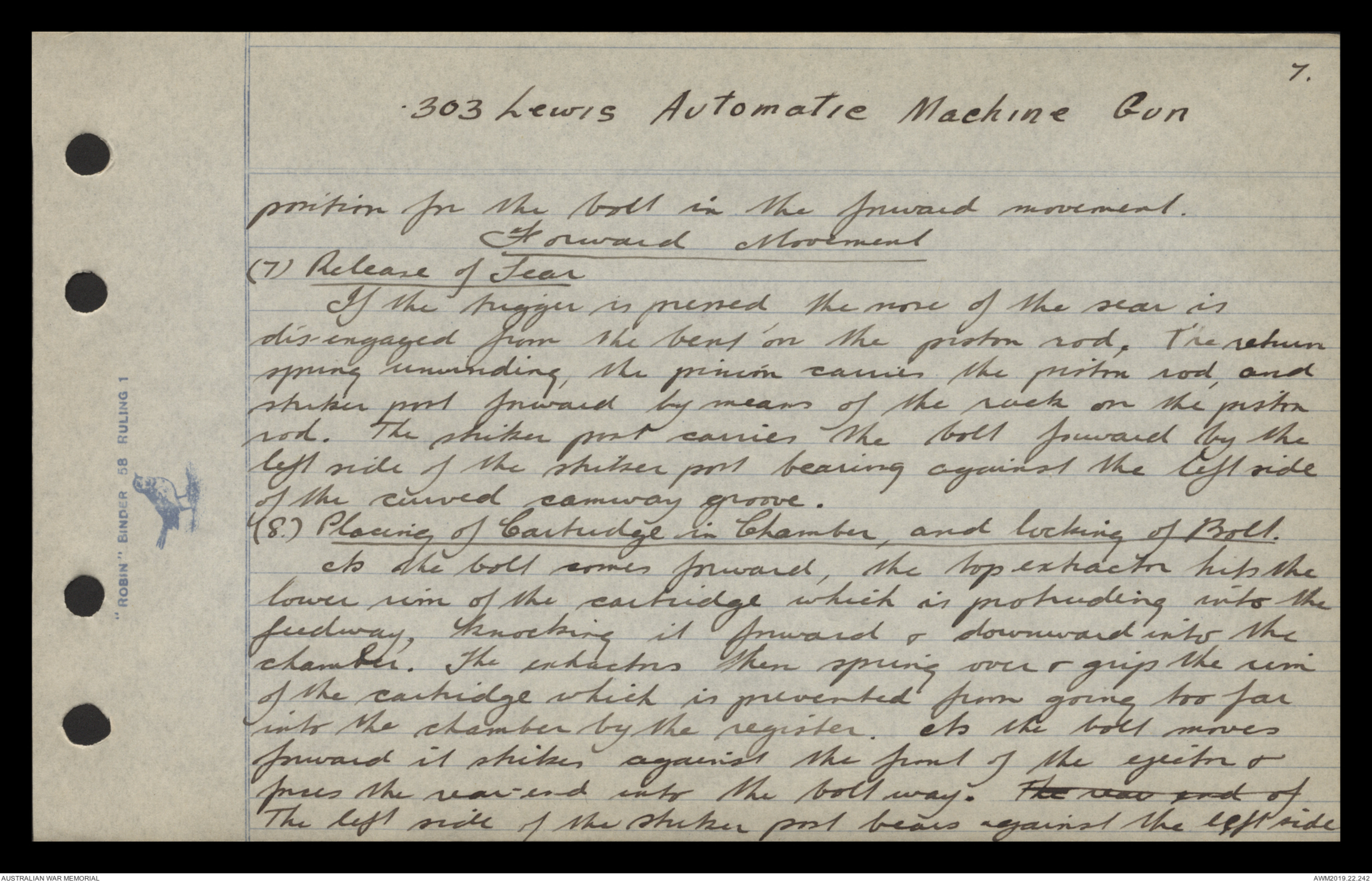
position for the bolt in the forward movement.
Forward Movement
(7) Release of Sear
If the trigger is pressed the nose of the sear is
dis-engaged from the bent on the piston rod. The return
spring unwinding, the pinion carries the piston rod, and
striker post forward by means of the rack on the piston
rod. The striker post carries the bolt forward by the
left side of the striker post bearing against the left side
of the curved camway groove.
(8) Placing of Cartridge in Chamber, and locking of Bolt.
As the bolt comes forward, the top extractor hits the
lower rim of the cartridge which is protruding into the
feedway, knocking it forward & downward into the
chamber. The extractors then spring over & grip the rim
of the cartridge which is prevented from going too far
into the chamber by the register. As the bolt moves
forward it strikes against the front of the ejector &
forces the rear-end into the bolt way. The rear end of
The left side of the striker post bears against the left side
8.
.303 Lewis Automatic Machine Gun
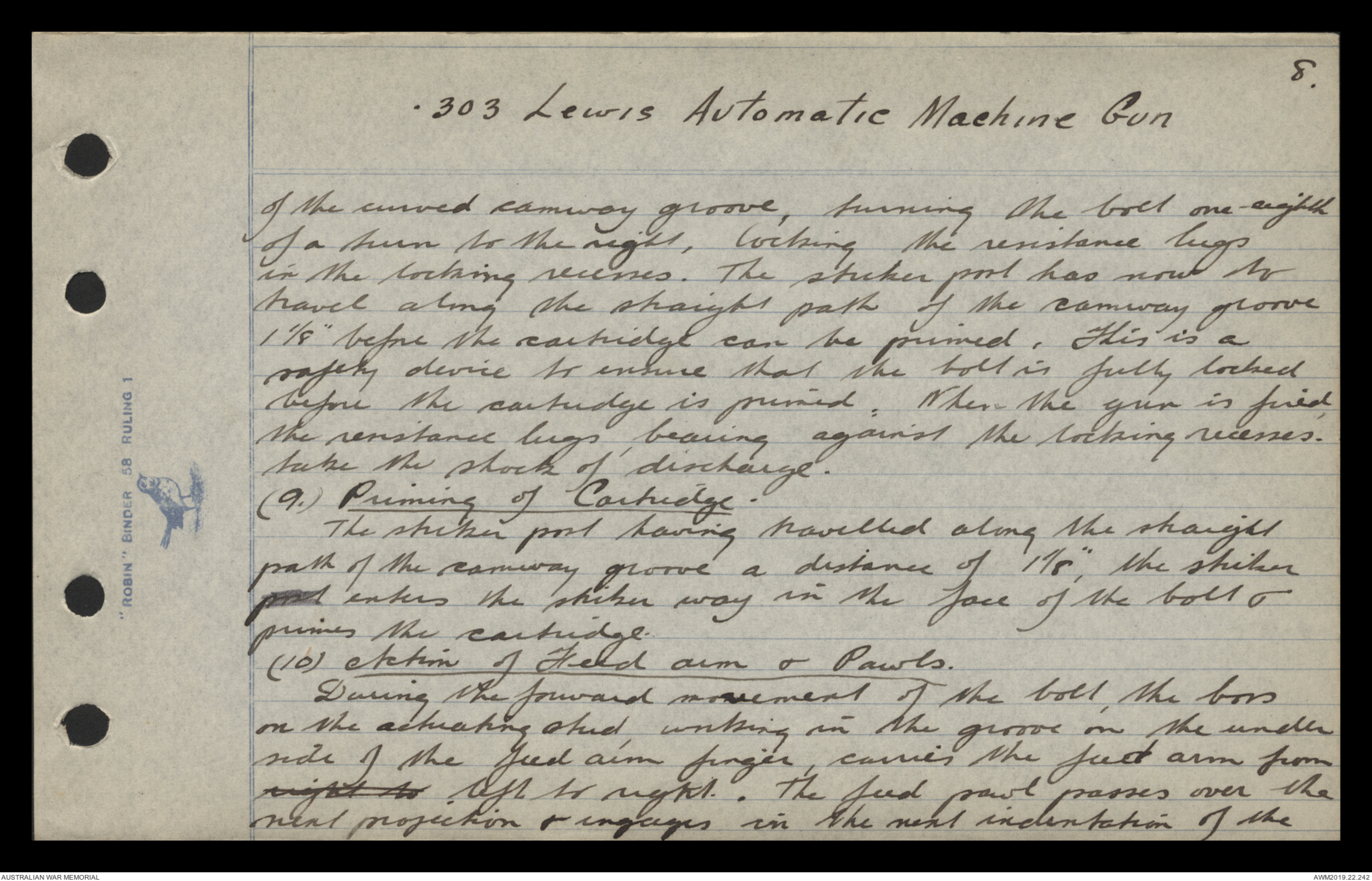
of the curved camway groove, turning the bolt one-eighth
of a turn to the right, locking the resistance lugs
in the locking recesses. The sticker pool has now to
travel along the straight path of the camway groove
1 1/8" before the cartridge can be primed. This is a
safety device to ensure that the bolt is fully locked
before the cartridge is primed. When the gun is fired,
the resistance lugs, bearing against the locking recesses.
take the shock of discharge.
(9.) Priming of Cartridge.
The striker post having travelled along the straight
path of the camway groove a distance of 1 1/8", the striker
post enters the striker way in the face of the bolt &
primes the cartridge.
(10) Action of Feed aim & Pawls.
During the forward movement of the bolt, the boss
on the actuating stud, working in the groove on the under
side of the feed arm finger, carries the feed arm from
right to left to right. The feed pawl passes over the
next projection & engages in the next indentation of the
9.
.303 Lewis Automatic Machine Gun
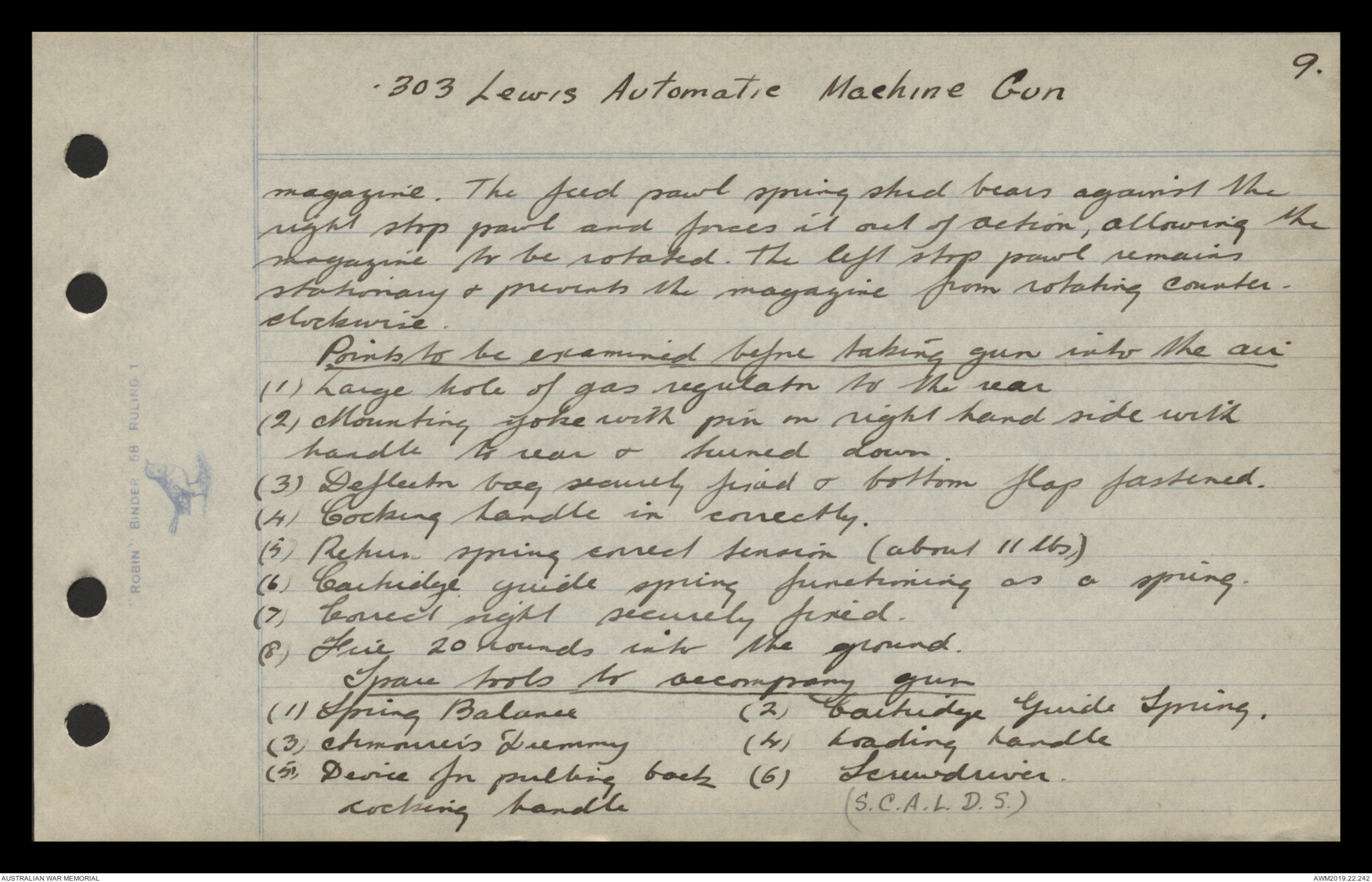
magazine. The feed pawl spring stud bears against the
right stop pawl and forces it out of action, allowing the
magazine to be rotated. The left stop pawl remains
stationary & prevents the magazine from rotating counter-clockwise.
Points to be examined before taking gun into the air
(1) Large hole of gas regulator to the rear
(2) Mounting yoke with pin in right hand side with
handle to rear & turned down.
(3) Deflector bag securely fixed & bottom flap fastened.
(4) Cocking handle in correctly.
(5) Return spring correct tension (about 11 lbs)
(6) Cartridge guide spring functioning as a spring.
(7) Correct sight securely fixed.
(8) Fire 20 rounds into the ground.
Spare tools to accompany gun
(1) Spring Balance (2) Cartridge Guide Spring.
(3) Armourer's Dummy (4) Loading handle
(5) Device for pulling back (6) Screwdriver
cocking handle (S.C.A.L.D.S.)
10.
.303 Lewis Automatic Machine Gun
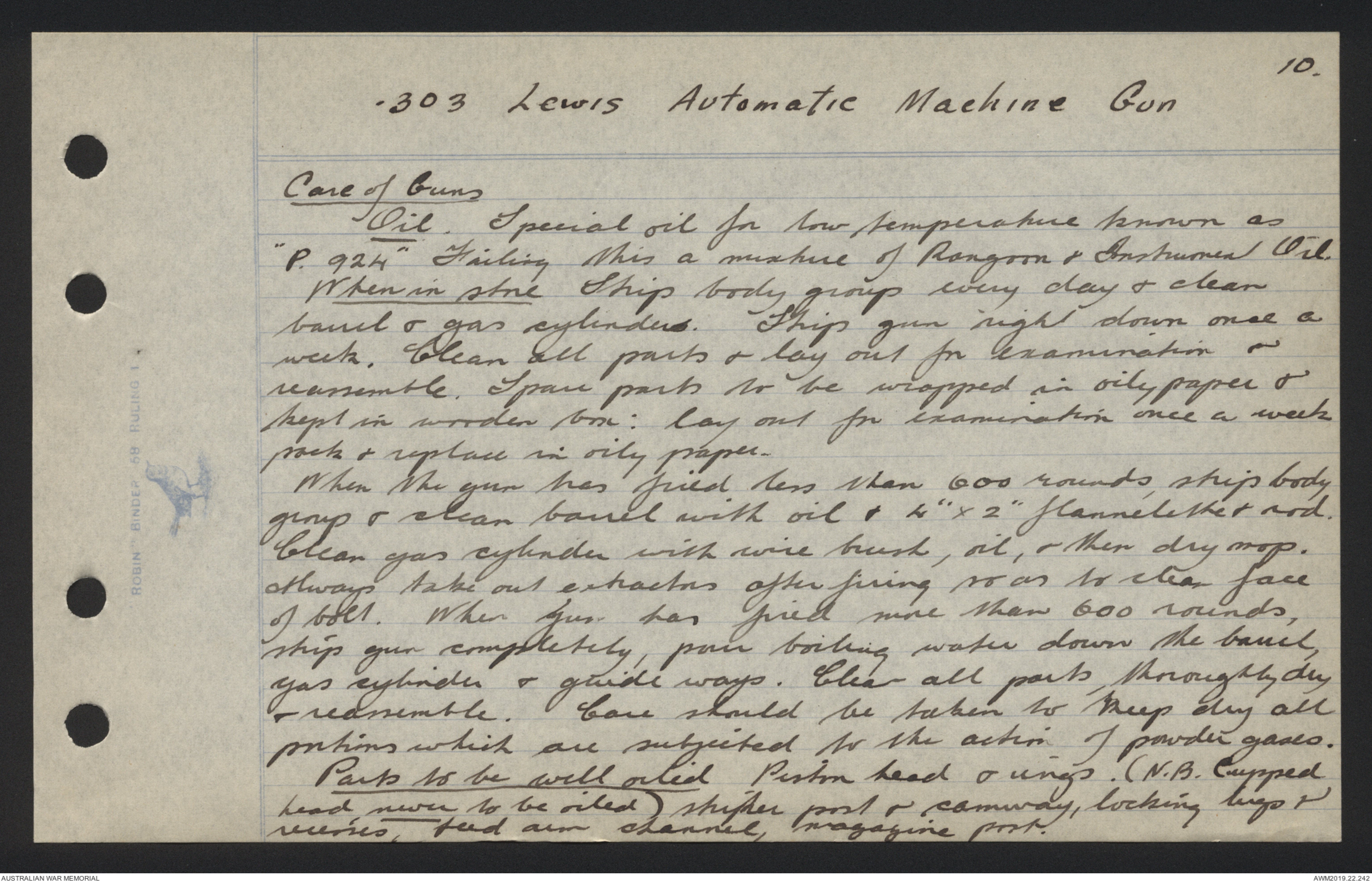
Care of Guns
Oil. Special oil for low temperature known as
"P. 924" Failing this a mixture of Rangoon & Instrument Oil.
When in store Strip body group every day & clean
barrel & gas cylinders. Strip gun right down once a
week. Clean all parts & lay out for examination &
reassemble. Spare parts to be wrapped in oily paper &
kept in wooden box: lay out for examination once a week
pack & replace in oily paper.
When the gun has fired less than 600 rounds, strip body
group & clean barrel with oil & 4" x 2" flannelette & rod.
Clean gas cylinder with wire brush, oil, & then dry mop.
Always take out extractors after firing so as to clean face
of bolt. When gun has fired more than 600 rounds,
strip gun completely, pour boiling water down the barrel,
gas cylinder & guide ways. Clean all parts, thoroughly dry
& reassemble. Care should be taken to keep dry all
portions which are subjected to the action of powder gases.
Parts to be well oiled Piston head & rings. (N.B. Cupped
head, never to be oiled) striker post & camway, locking lugs &
recesses, feed aim channel, magazine post.
11.
.303 Lewis Automatic Machine Gun
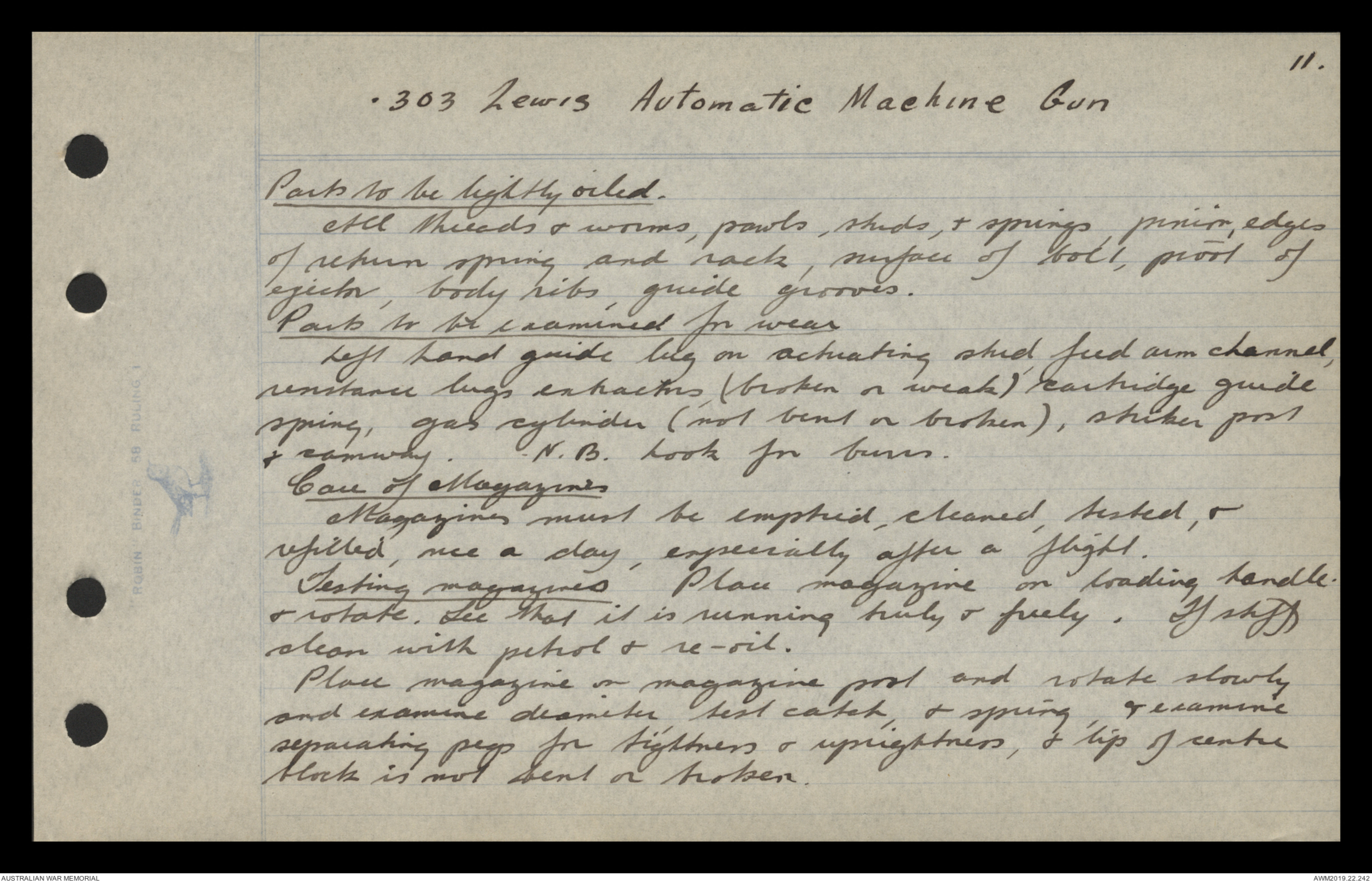
Parts to be lightly oiled.
All threads & worms, pawls, skids, & springs, pinion, edges
of return spring and rack, surface of bolt, proof of
ejector, body ribs, guide grooves.
Parts to be examined for wear
Left hand guide lug on actuating skid feed arm channel,
resistance lugs extractors (broken or weak) cartridge guide
spring, gas cylinder (not bent or broken), striker post
& camway. N.B. Look for burrs.
Care of Magazines
Magazines must be emptied, cleaned, tested, &
refilled, once a day, especially after a flight.
Testing magazines Place magazine on loading handle.
& rotate. See that it is running truly & freely. If stiff
clean with petrol & re-oil.
Place magazine on magazine pool and rotate slowly
and examine diameter, test catch, & spring, & examine
separating pegs for tightness & uprightness, & tip of centre
block is not bent or broken.
12
.303 Lewis Automatic Machine Gun
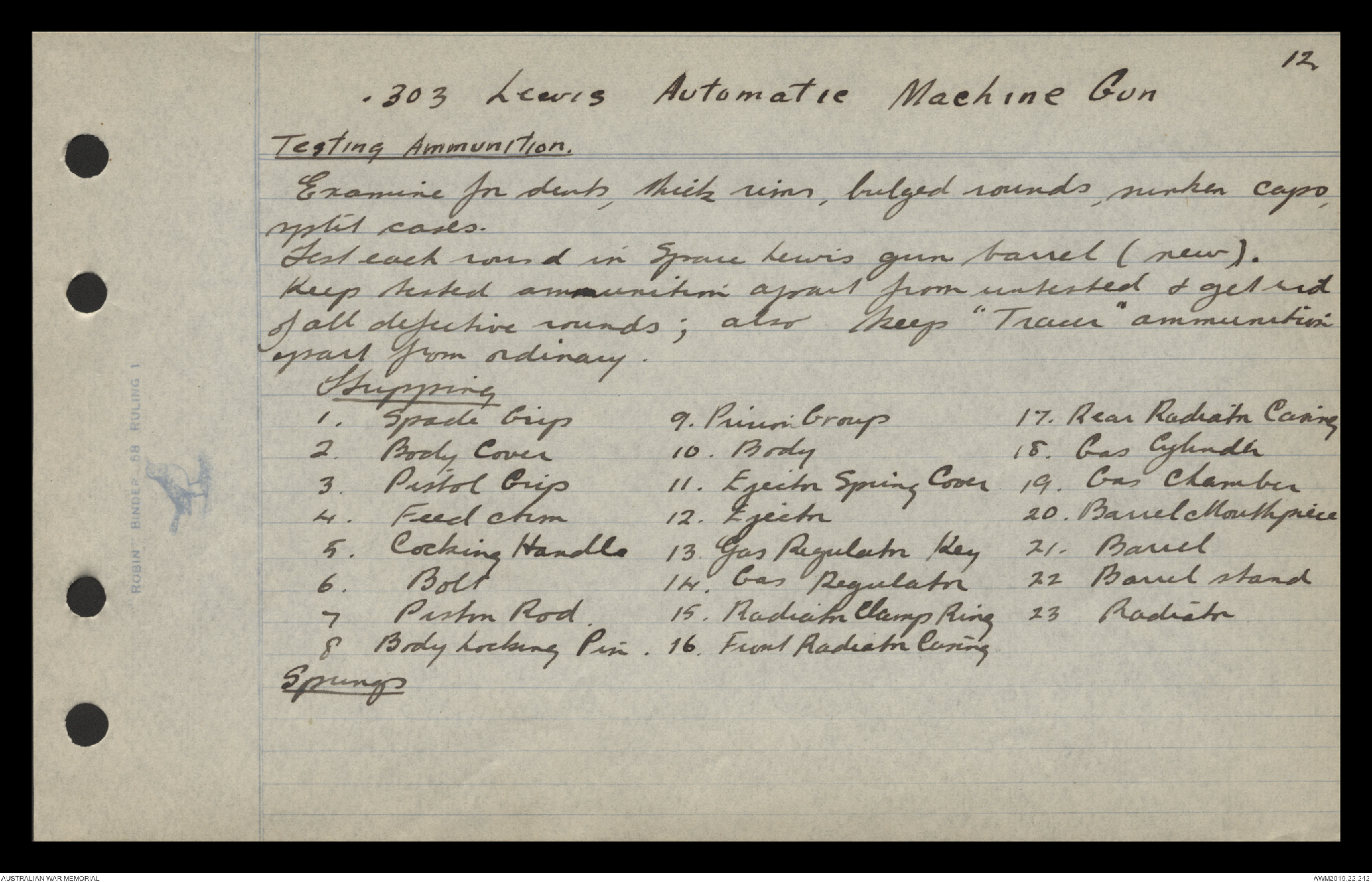
Testing Ammunition
Examine for dents, thick rims, bulged rounds, sunken caps,
split cases.
Test each round in Spare Lewis gun barrel (new).
Keep tested ammunition apart from untested & get rid
of all defective rounds; also keep "Tracer" ammunition.
apart from ordinary.
Stripping
1. Spade Grip 9. Pinion Group 17. Rear Radiator Casing
2. Body Cover 10. Body 18. Gas Cylinder
3. Pistol Grip 11. Ejector Spring Cover 19. Gas Chamber
4. Feed Arm 12. Ejector 20. Barrell Mouthpiece
5. Cocking Handle 13. Gas Regulator Key 21. Barrell
6. Bolt 14. Gas Regulator 22 Barrel stand
7 Pistol Rod 15. Radiator Clamp Ring 23 Radiator
8 Body Locking Pin 16. Front Radiator Casing
13.
.303 Lewis Automatic Machine Gun
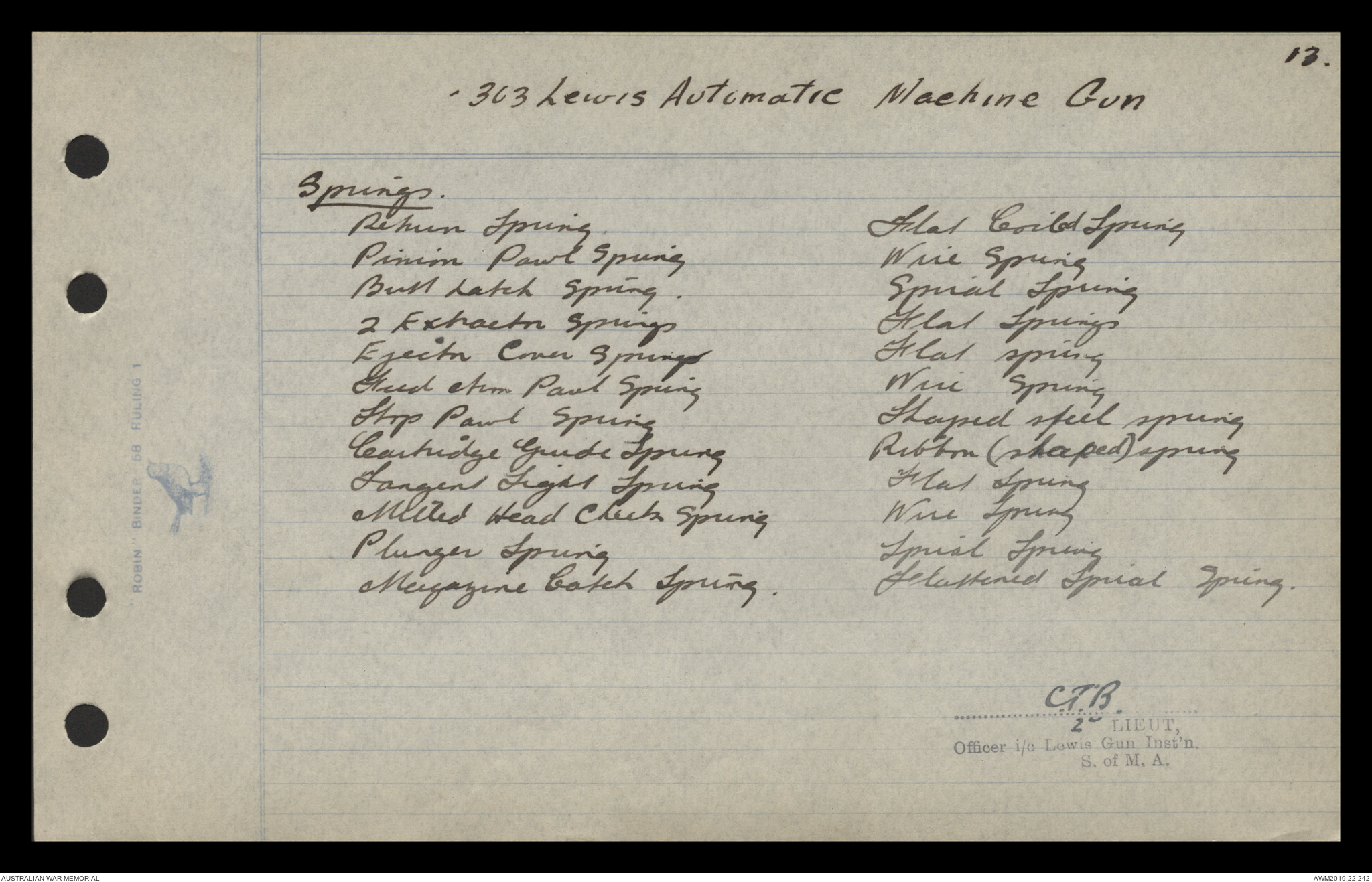
Springs.
Return Spring Flat Coiled Spring
Pinion Pawl Spring Wire Spring
Butt Latch Spring. Spiral Spring
2 Extractor Springs Flat Spring
Ejector Cover Springs Flat Spring
Feed Arm Pawl Spring Wire Spring
Stop Pawl Spring Shaped Steel Spring
Cartridge Guide Spring Ribbon (shaped) spring
Tangent Light Spring Flat Spring
Milled Head Check Spring Wire Spring
Plunger Spring Spiral Spring
Magazine Catch Spring Flattened Spiral Spring.
C.T.B
2nd LIEUT,
Officer i/c Lewis Gun Inst'n
S. of M. A.
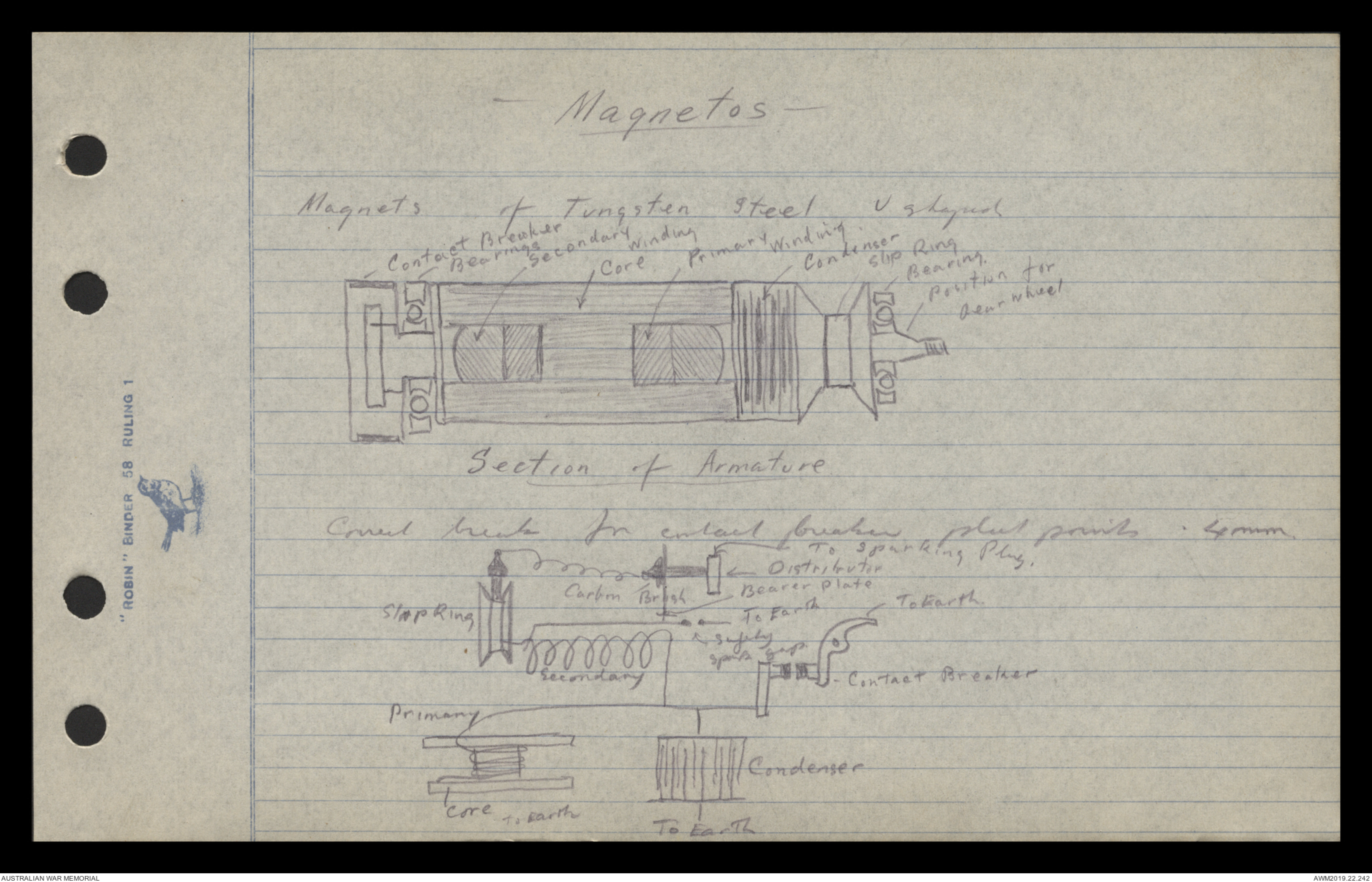
-Magnetos-
Magnets of Tungsten steel
Diagram ~ see original document
Section of Armature
Diagram ~ see original document
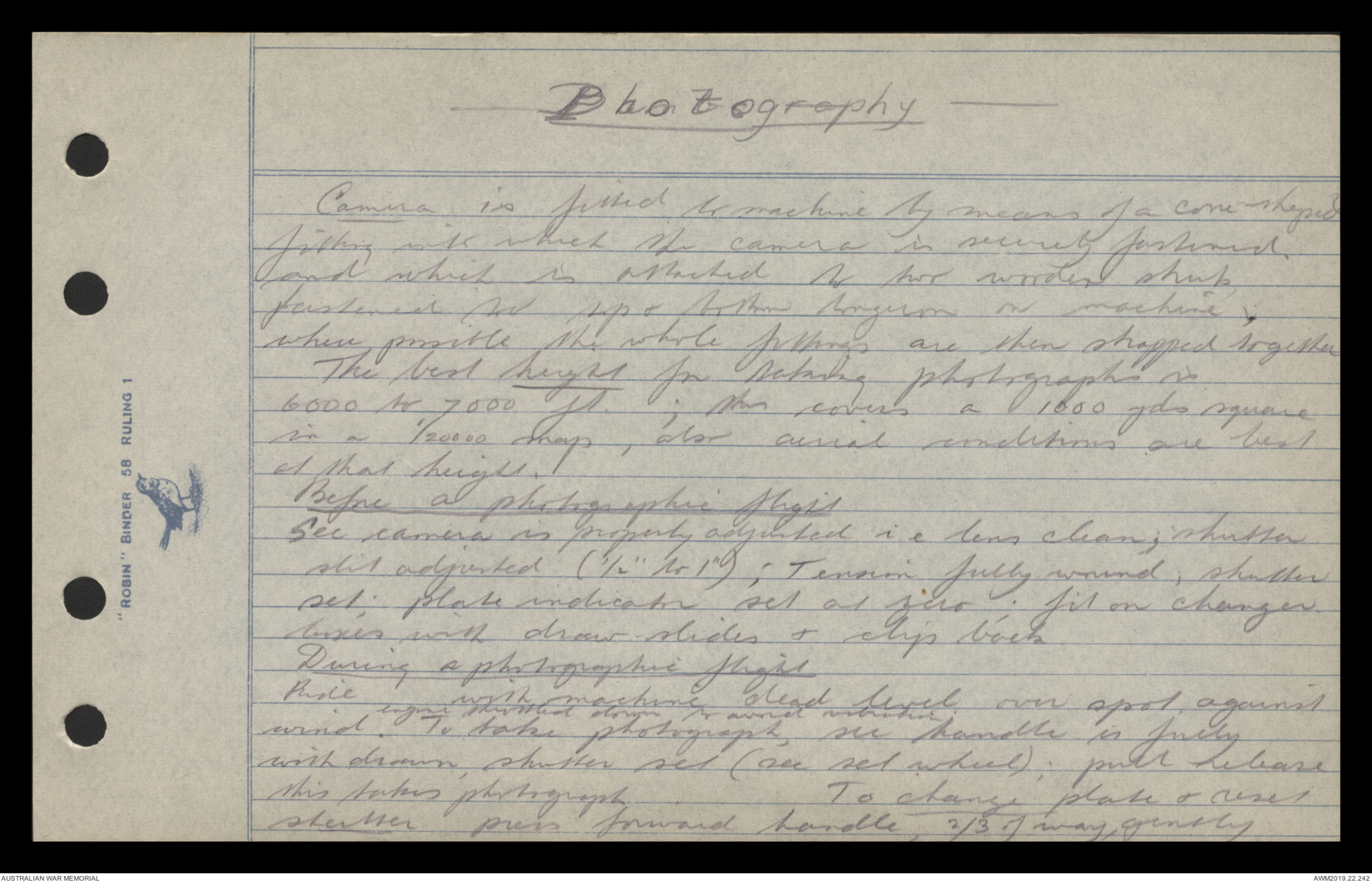
-Photography-
Camera is fitted to machine by means of a cone shaped
fitting with which the camera is securely fastened.
and which is attached to two wooden struts
fastened to top & bottom longeron on machine.
where possible the whole fittings are then strapped together
The best height for taking photographs is
6000 to 7000 ft. ; this covers a 1000 yds square
in a 1/20000 map, also arial conditions are best
at that height.
Before a photographic flight
See camera is properly adjusted i. e. lens clean; shutter
slit adjusted ( ½" to 1"); Tension fully wound; shutter
set; plate indicator set at zero; fit on charger
boxes with draw slides & clip back.
During a photographic flight
Ride with machine dead level over spot, against
wind. engine throttled down to avoid vibration To take photograph, see handle is fully
with drawn, shutter set (see set wheel); pull release
this takes photograph. To change plate & reset
shutter press forward handle, 2/3 of way, gently
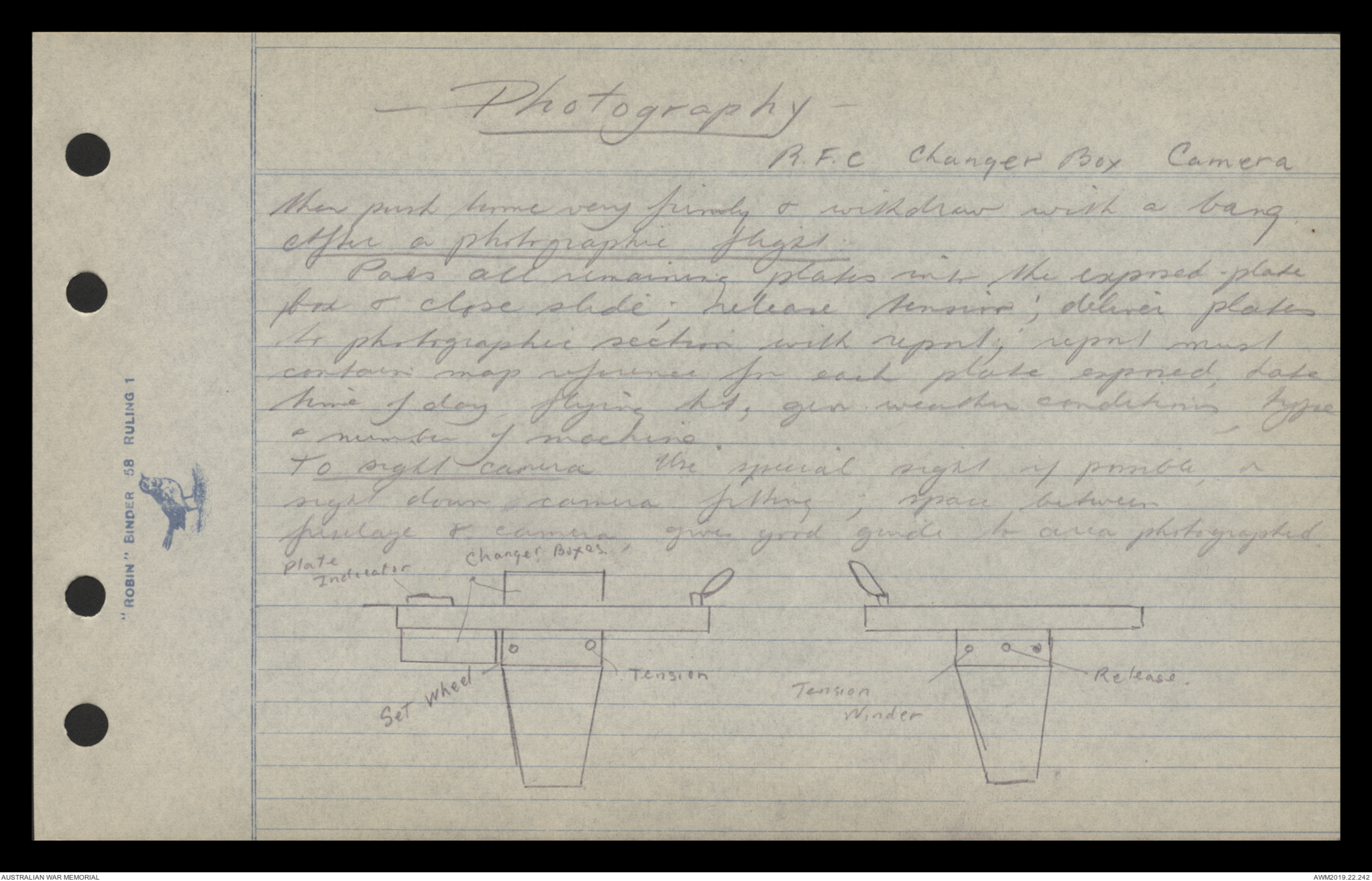
-Photography-
R.F.C Changer Box Camera
then push home very firmly & withdraw with a bang.
After a photographic flight
Pass all remaining plates into the expressed plate
box & close slide; release tension; deliver plates
to photographic section with report; report must
contain map reference for each plate exposed, date
time of day, flying ht; gen weather conditions, type
& number of machine.
To sight camera Use special sight if possible, or
sight down camera fitting; space between
fuselage & camera, gives good guide to area photographed.
Diagram ~ see original
 Loretta Corbett
This transcription item is now locked to you for editing. To release the lock either Save your changes or Cancel.
This lock will be automatically released after 60 minutes of inactivity.