Service notebook of Harold Gordon Cornell - 1917 - Part 3
1.
120 H.P. Beardmore
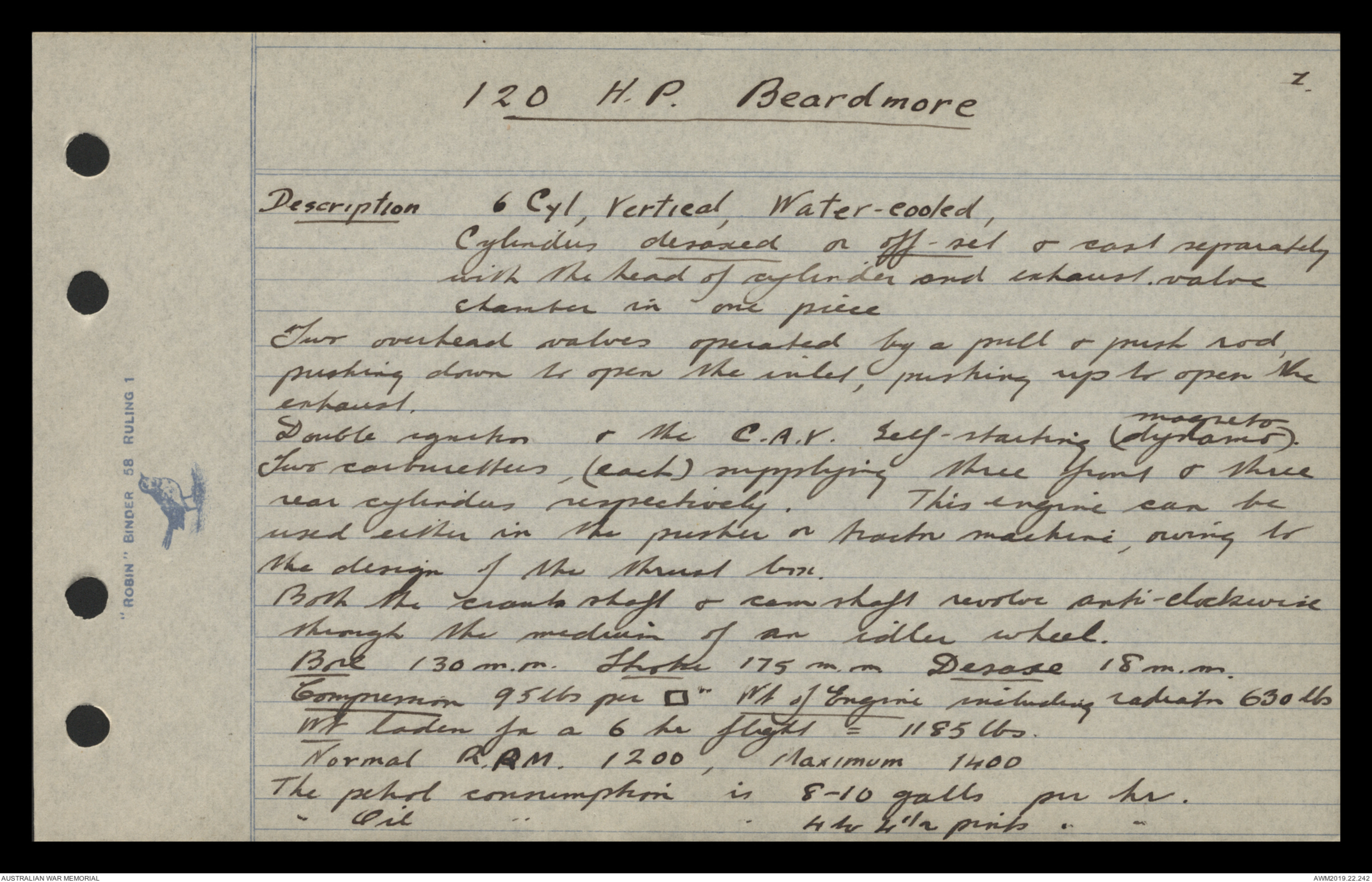
Description 6 Cyl, Vertical, Water-cooled,
Cylinders desaxed or off-set & cast separately
with the head of cylinder and exhaust, valve
chanter in one piece
Two overhead valves operated by a pull & push rod
pushing down to open the inlet pushing up to open the
exhaust
Double ignition & the C.A.V. Self-starting (magneto dynamo).
Two carburetters, (each) supplying three front & three
rear cylinders respectively. This engine can be
used either in the pusher or tractor machine, owing to
the design of the thrust box.
Both the crank shaft & cam shaft revolve anti-clockwise
through the medium of an idler wheel.
Bore 130 m.m. Throtle 175 m.m. Desaxe 18 m.m
Compression 95 lbs per ▢" Wt of Engine including radiator
630 lbs
Wt laden for a 6 hr flight = 1185 lbs,
Normal R.P.M. 1200, Maximum 1400
The petrol consumption is 8 - 10 galls per hr.
'' oil " " 4 to 4½ pints
2.
120 H.P. Beardmore
Both the centrifugal water pump & Borsch lubricator are
fixed at rear of engine & driven direct off the crank-shaft.
at engine speed
The order of firing is 1, 5, 3, 6, 2, 4. (distributes
explosion stress equally over all bearings
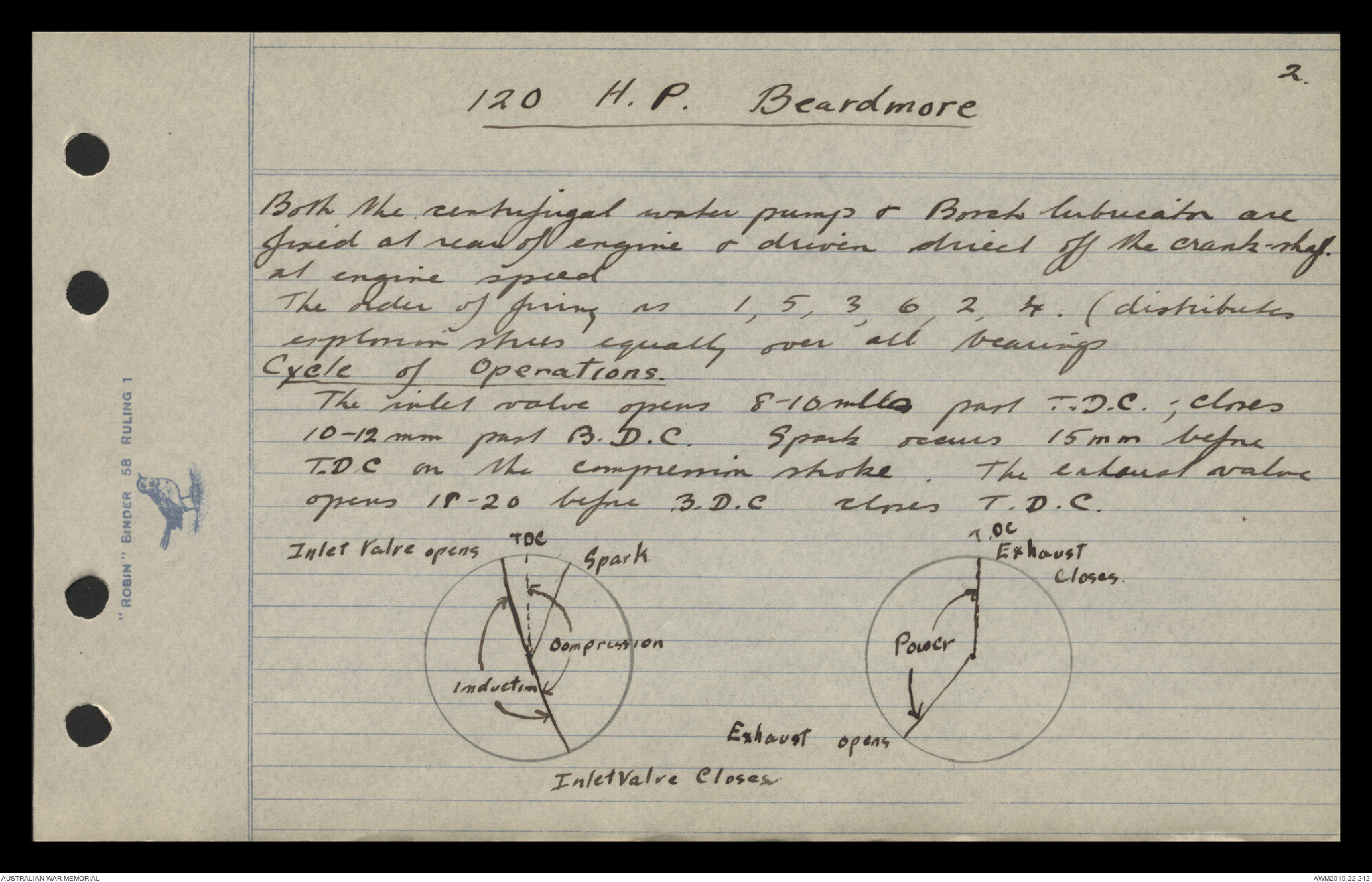
Cycle of Operations.
The inlet valve opens 8-10 mls past T. D.C.; closes
10-12 mm past B.D.C. Spark occurs 15 m m before
T.D.C. on the compression stroke. The exhaust valve
opens 18-20 before B.D.C closes T.D.C.
Hand drawn diagrams - see original document
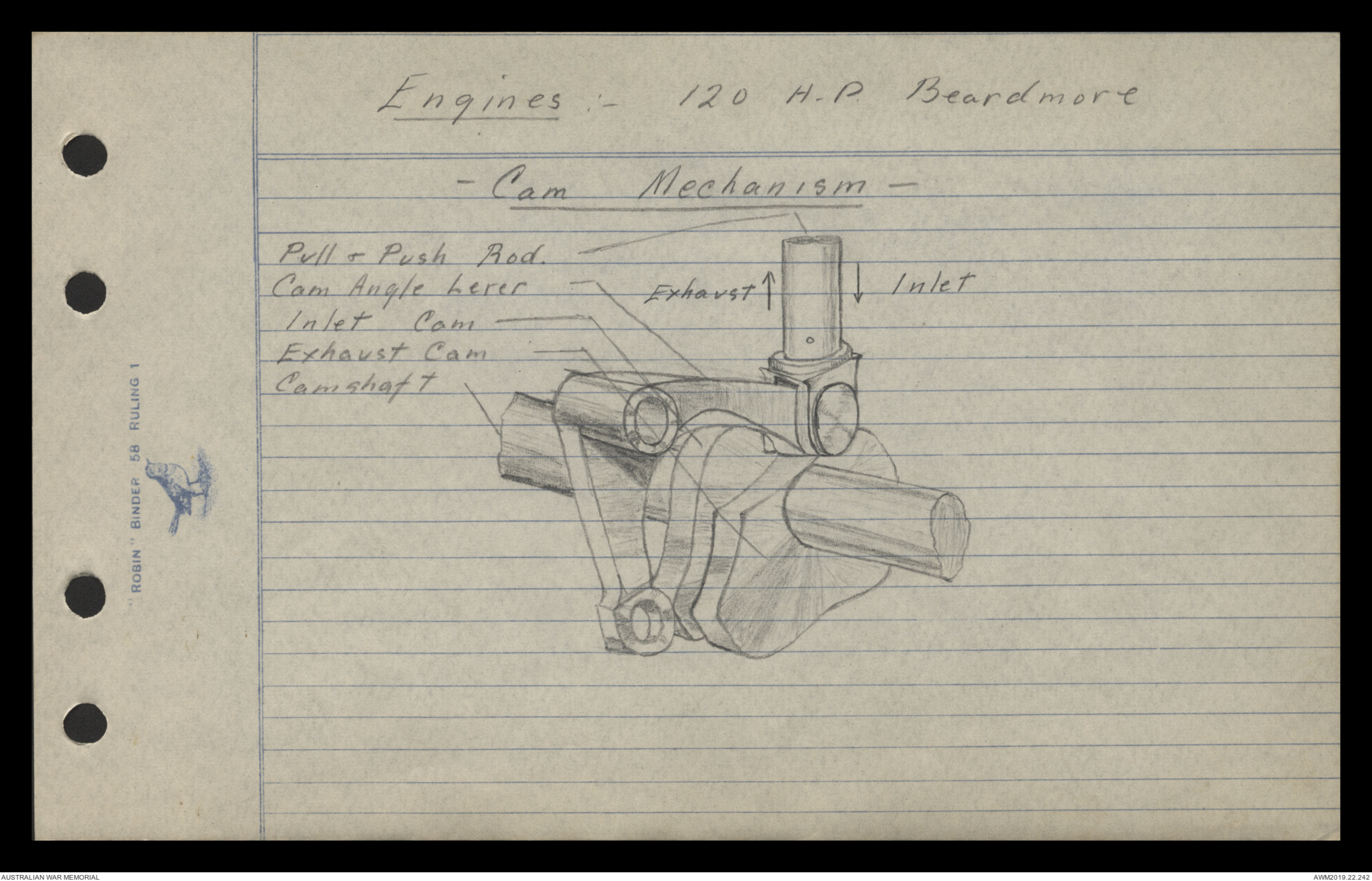
Engines: - 120 H.P. Beardmore
- Cam Mechanism
Hand drawn diagram - see original document
Pull & Push Rod.
Cam Angle Lever
Inlet Cam
Exhaust Cam
Camshaft
Exhaust ↑
Inlet ↓
3
120 H. P. Beardmore
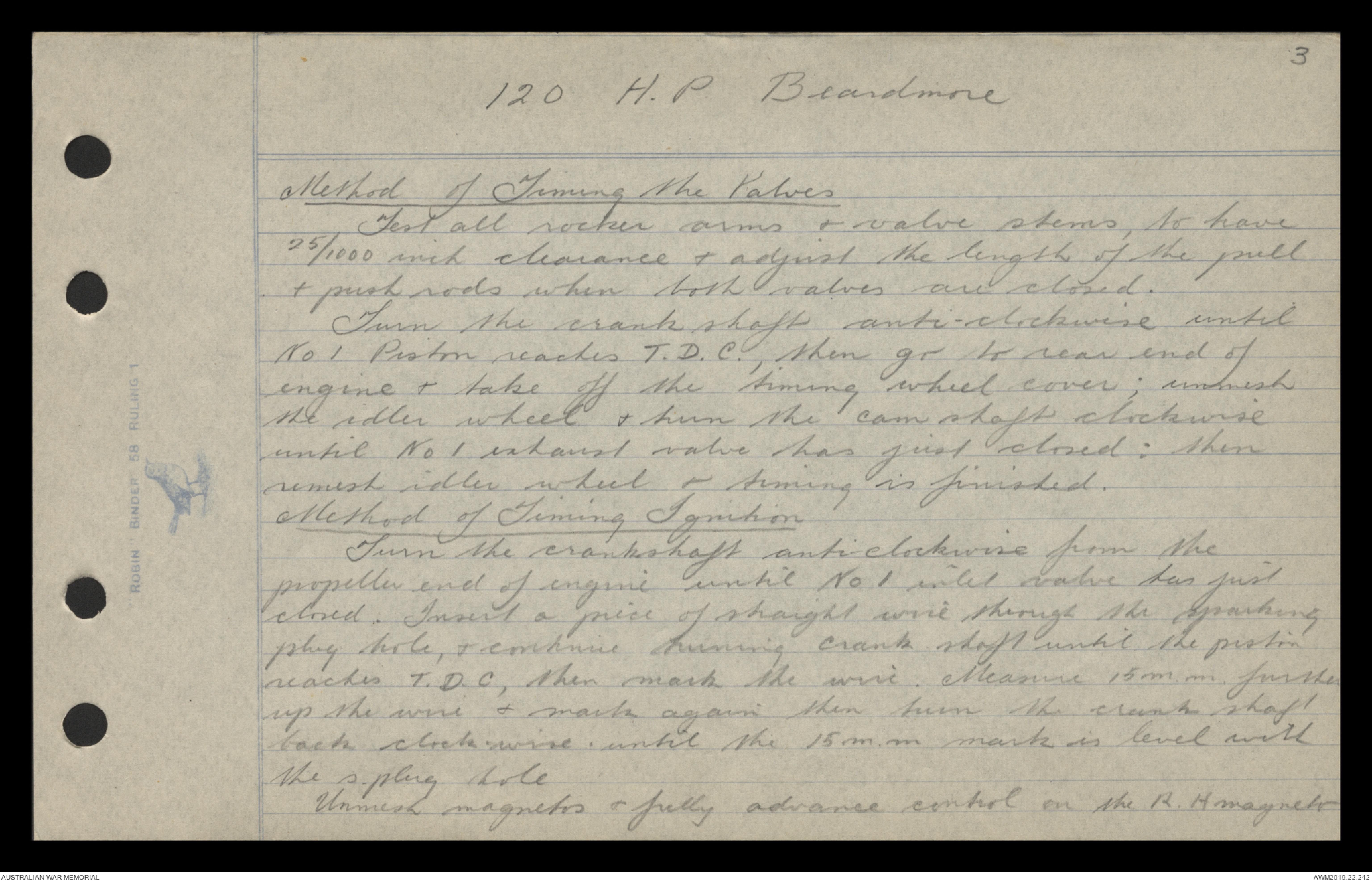
Method of Timing the Valves
Test all rocker arms & valve stems, to have
25/1000 inch clearance & adjust the length of the pull
& push rods when both valves are closed.
Turn the crank shaft anti-clockwise until
No 1 Piston reaches T. D. C., then go to rear end of
engine & take off the timing wheel cover; unmesh
the idler wheel & turn the cam shaft clockwise
until No 1 exhaust valve has just closed: then
remesh idler wheel & timing is finished.
Method of Timing Ignition
Turn the crankchaft anti-clockwise from the
propeller end of engine until No 1 inlet valve has just closed.
Insert a piece of straight wire through the sparking
plug hole, & continue turning crank shaft until the piston
reaches T.D.C., then mark the wire. Measure 15 m.m. further
up the wire & mark again them turn the crank-shaft
back clock-wise until the 15 m.m. mark is level with
the s.plug hole.
Unmesh magnets & fully advanced control on the R.H. magneto
4.
120 H. P. Beardmore
& turn the armature shaft until the carbon brush is
on No 1 segment with the platinum points just breaking
then remesh that magneto & synchronise l.h. magneto
to r.h. magneto. Care to be taken that the Pt.
points of each magneto are breaking at exactly the
same moment.
Valve Gear:-
The valves are operated by a single pull & push rod,
pivoted leaf-spring & overhead rocker. At the lower
end of the pull & push rod is fixed a cam-angle
lever which is pivoted to the crank case; & in
contact with the cam angle levers; the exhaust cam
pushes up to open the exhaust valve & the inlet cam
pulls down to open the inlet valve. Both
valves lift 7. 5 . m.m.
Water cooling
Advantages
Reduces oil consumption
Hot water round carburetters
Even temp of cylinder walls, cooler exhaust
Disadvantages
Heat resistance greater (of radiator)
Greater weight
Liability of leakage
Cylinder Walls ¼" thick
Water Jackets 1½m m thick
Space between jackets 3⁄8 "
Concave Piston Head
Advantage Force of explosion directed nearer to
centre, sans wear & tear in bearings.
Disadvantage Weakens
Causes preignition
5
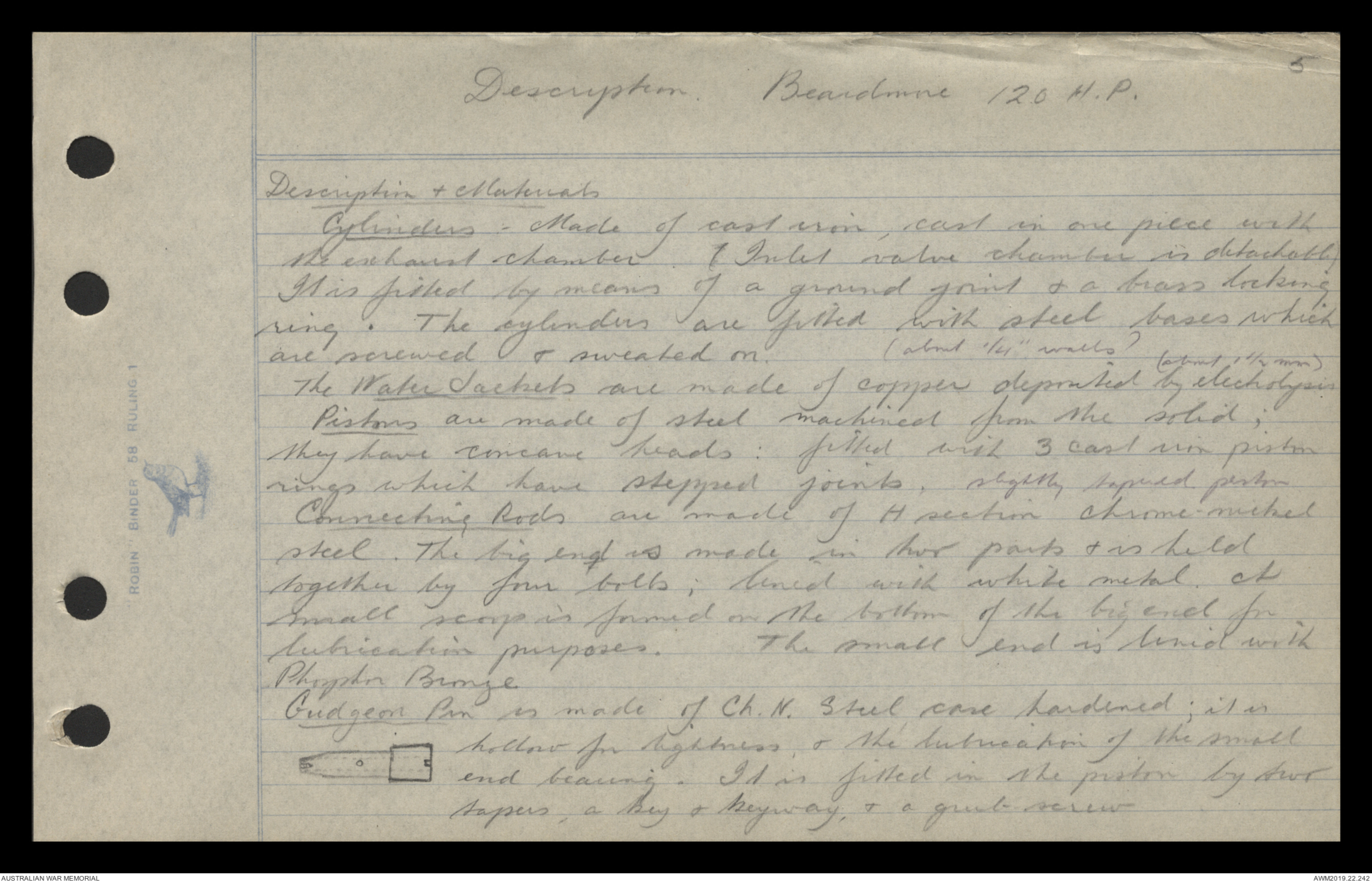
Description Beardmore 120 H.P.
Description & Materials
Cylinders - Made of cast iron, cast on one piece with
the exhaust chamber I Inlet valve chamber is detachable.
It is filled by means of a ground joint & a brass locking
ring. The cylinders are fitted with steel bases which
are screwed & sweated on. (about ¼"walls)
The Water Jackets are made of copper deposited by (about 1½ mm) by electrolysis
Pistons are made of steel machined from the solid;
they have concave heads: filled with 3 cast iron piston
rings which have stepped joints, slightly tapered piston
Connecting Rods are made of H section chrome-nickel
steel. The big end is made in four parts & is held
together by four bolts, lined with white metal. A
small scoop is formed on the bottom of the big end for
lubrication purposes. The small end is lined with
Phosphor Bronze.
Gudgeon Pin is made of Ch. N. Steel case hardened; it is
Hand drawn diagram - see original document
hollow for lightness, & the lubrication of the small
end bearing . It is fitted in the piston by four
tapers, a key & keyway, & a grub screw.
6
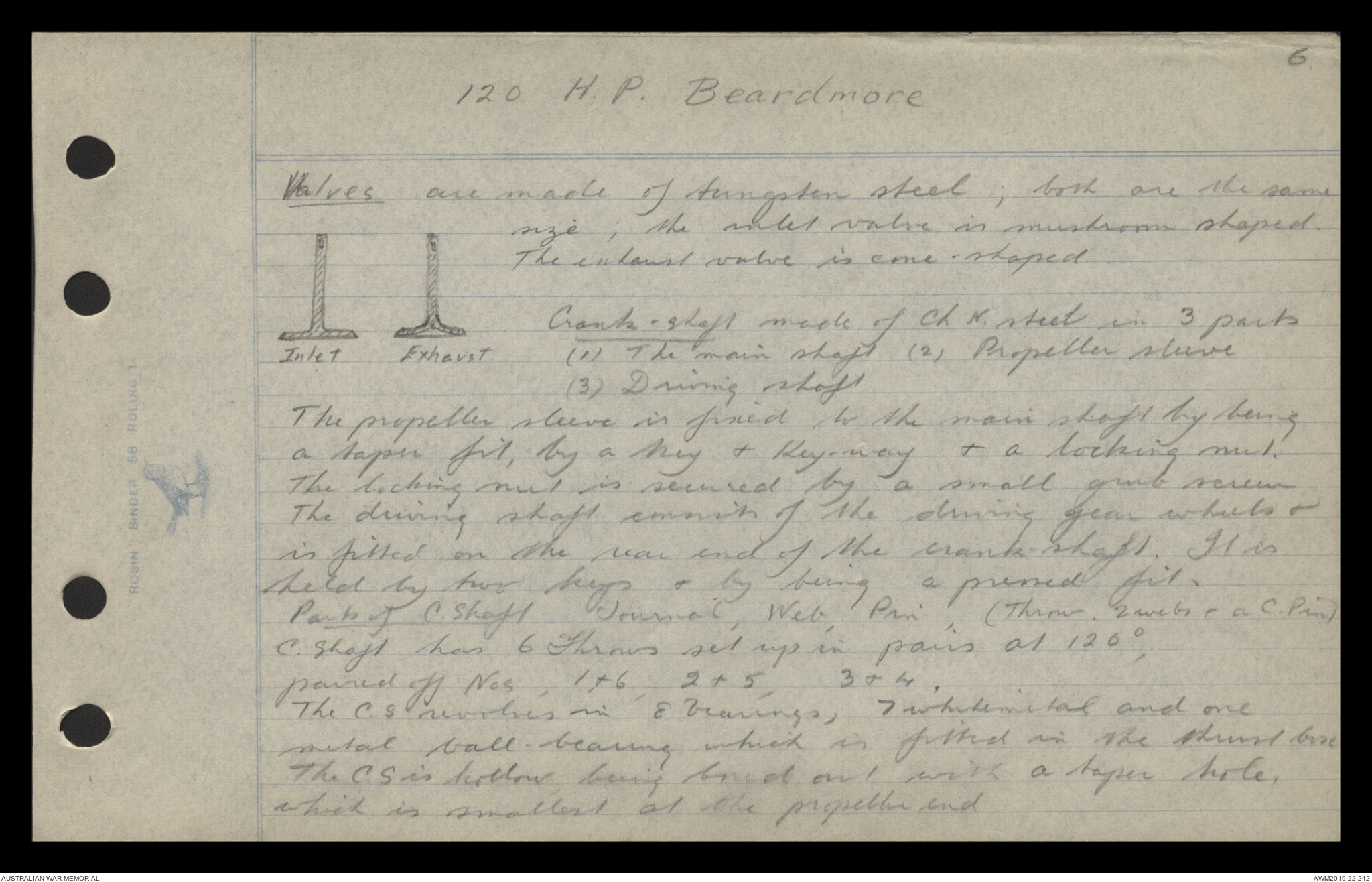
120 H. P. Beardmore
Valves are made of tungsten steel, both are the same
size, the inlet valve is mushroom shaped.
The exhaust valve is cone-shaped.
Hand drawn diagram - see original document
Inlet Exhaust
Crank-shaft made of Ch. N. steel in 3 parts
(1) The main shaft (2) Propeller sleeve
(3) Driving shaft
The propeller sleeve is fixed to the main shaft by being
a taper fit, by a key & Key-way & a locking nut.
The locking nut is secured by a small grub screw
The driving shaft consists of the driving gear wheels &
is fitted on the rear end of the crank-shaft. It is
held by two keys & by being a pressed fit.
Parts of C. Shaft. Journal, Web, Pin, ( Throw. 2 webs & a C. Pin)
C.Shaft has 6 Throws set up in pairs at 120°,
paired off Nos, 1 & 6, 2 & 5, 3 & 4.
The C.S. revolves in 8 bearings, 7 whitemetal and one
metal ball-bearing which is fitted in the thrust bore
The C.S. is hollow being bored out with a taper hole.
which is smallest at the propeller end
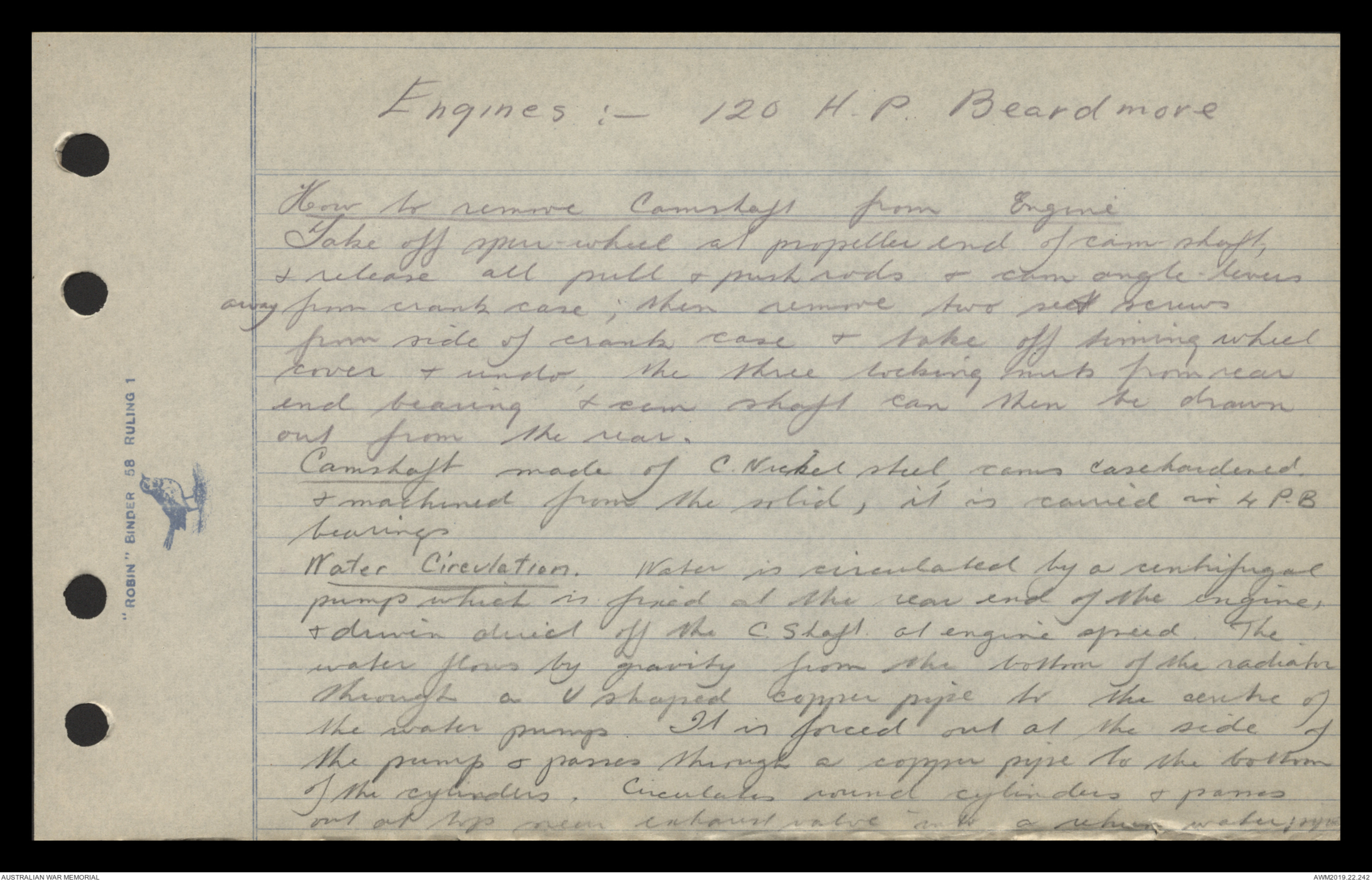
Engines:- 120 H. P. Beardmore
How to remove Camshaft from Engine
Take off open-wheel at propeller end of cam shaft,
& release all pull and push rods - cam angle-levers
away from crank case; then remove two set screws
from side of crank case & take off timing wheel
cover & under the three locking nuts from rear
end bearing & cam shaft can then be drawn
out from the rear.
Camshaft made of C. Nickel steel, cams casehardened
& machined from the solid, it is carried in 4 P.B.
bearings.
Water Circulation. Water is circulated by a centrifugal
pump which is fixed at the rear end of the engine,
& driven direct off the C. Shaft at engine speed. The
water flows by gravity from the bottom of the radiator
through a U shaped copper pipe to the centre of
the water pump. It is forced out at the side of
the pump and passes through a copper pipe to the bottom
of the cylinders. Circulates round cylinders & passes
out Wp. near exhaust valve into a return water pipe
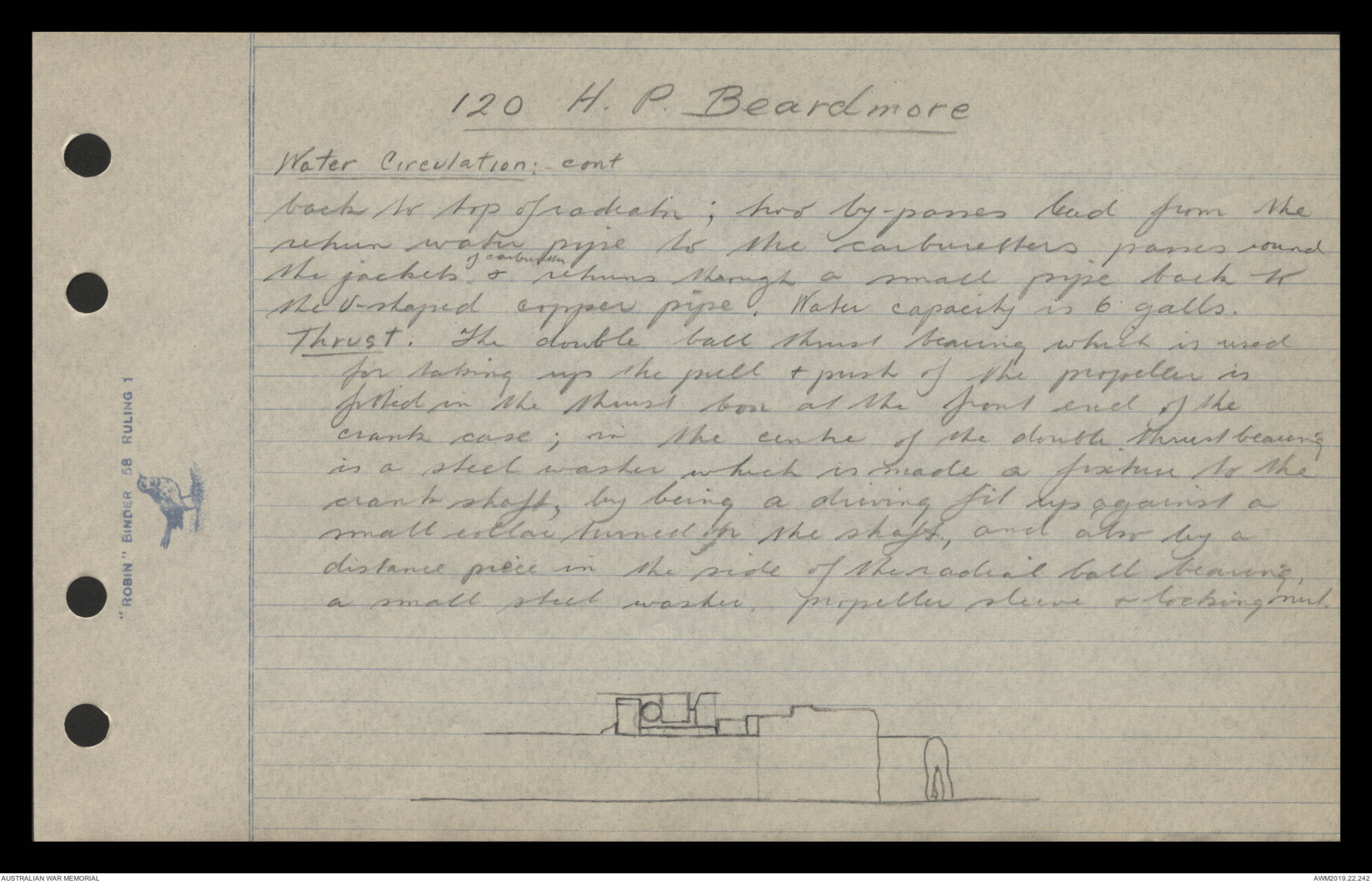
120 H. P. Beardmore
Water Circulation: -cont
back to top of radiator; two by-passes lead from the
return water pipe to the carburetters, passes round
the jackets of carburetters & returns through a small pipe back to
the U-shaped copper pipe. Water capacity is 6 galls.
Thrust. The double ball thrust bearing which is used
for taking up the pull & push of the propeller is
fitted in the thrust box at the front end of the
crank case; in the centre of the double thrust bearing
is a steel washer which is made a fixture to the
crank shaft, by being a driving fit up against a
small collar turned on the shaft, and also by a
distance piece in the side of the radial ball bearing,
a small steel washer, propeller sleeve & locking nut.
Hand drawn diagram - see original document
 Jen
Jen This transcription item is now locked to you for editing. To release the lock either Save your changes or Cancel.
This lock will be automatically released after 60 minutes of inactivity.