Notebook of James Stuart Leslie Ross - Part 2
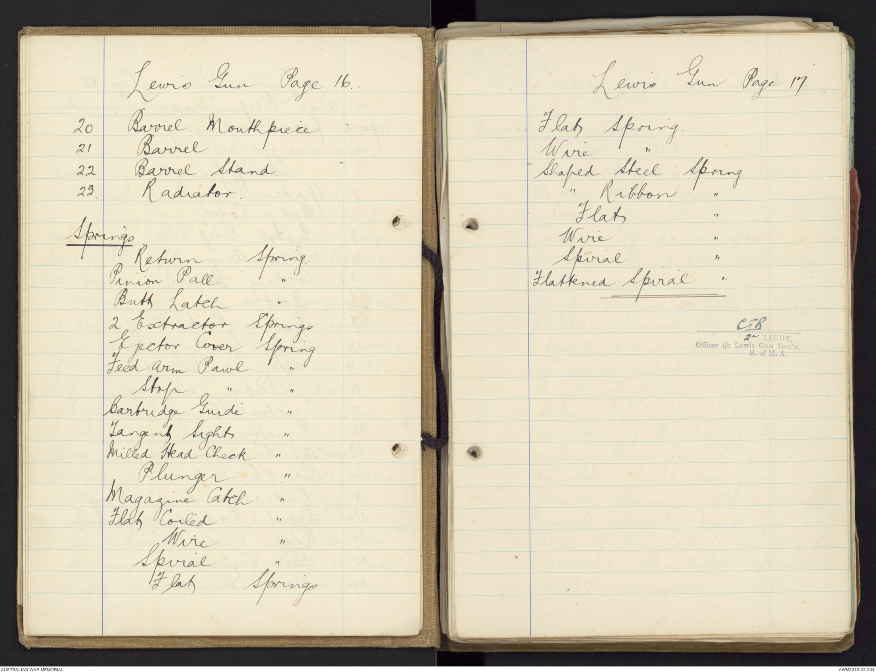


Lewis Gun Page 16.
20 Barrel Mouthpiece
21 Barrel
22 Barrel Stand.
23. Radiator.
Springs
Return Spring.
Pinion Pall "
Butt Latch "
2 Extractor Springs
Ejector Cover Spring
Feed Arm Pawl "
Stop " "
Cartridge Guide "
Tangent Sight ''
Milled Head Check "
Plunger "
Magazine Catch "
Flat Coiled "
Wire "
Spiral "
Flat Springs
Lewis Gun Page 17.
Flat Spring.
Wire "
Shaped Steel Spring
" Ribbon "
Flat "
Wire "
Spiral "
Flattened Spiral "
CIB
2nd LIEUT,
Officer i/c Lewis Gun Inst'n
S. of M.A.
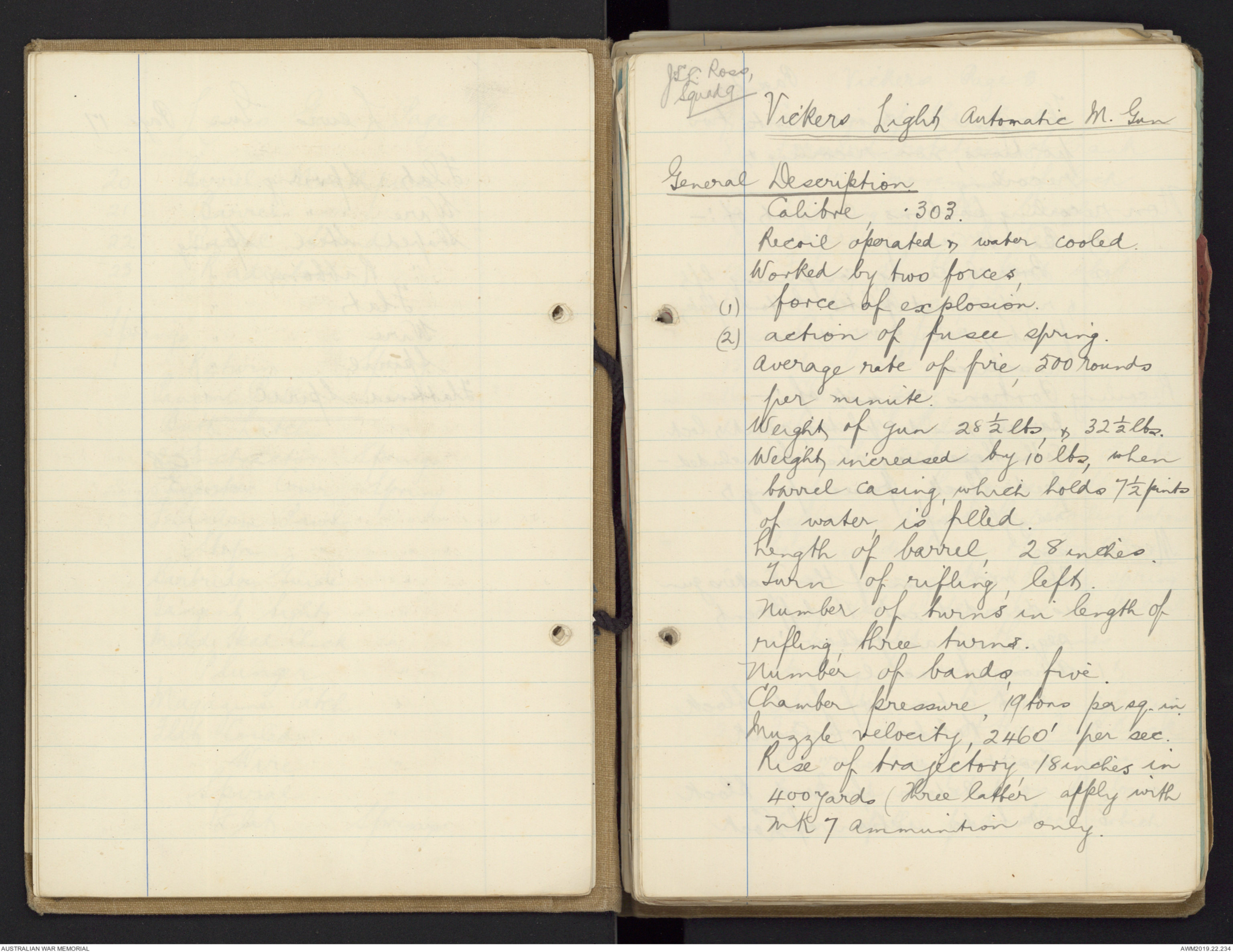
[*JSL. Ross,
Squad 9*]
Vickers Light Automatic M. Gun
General Description
Calibre, .303.
Recoil operated & water cooled.
Worked by two forces,
(1) force of explosion.
(2) action of fusee spring.
Average rate of fire, 500 rounds
per minute.
Weight of gun 28½ lbs, & 32½ lbs.
Weight increased by 10 lbs, when
barrel casing, which holds 7½ pints
of water is filled.
Length of barrel, 28 inches.
Turn of rifling, left.
Number of turns in length of
rifling, three turns.
Number of bands, five.
Chamber pressure, 19 tons per sq. in.
Muzzle velocity, 2460' per sec.
Rise of trajectory, 18 inches in
400 yards (Three latter apply with
Mk 7 ammunition only.
Page 2.
The gun is divided into two
portions, non-recoiling &
recoiling.
Non-recoiling portions consists of :-
(1) Barrel Casing.
(2) Breach Casing, comprising left
& right outside plates, bottom plate,
front & rear cover & rear
crosspiece.
Recoiling Portions consists of :-
Barrel, inside plates, crank & lock.
With these may also be included -
feed block, fusee spring &
muzzle cup.
Mechanism.
The mechanism of the Vickers gun
is divided into 16 different
sequences as follows :-
1. Action of recoil
2. First action of feed block
3. " Rotation of Crank.
4 Second " " "
5 " Action of Feed Block
6. Outside action of Lock
Vickers Page 3.
7. Cocking of the Lock
8. Forward rotation of Crank
9. " movement of lock
10. Closing of the breech
11 Depression of Sear
12 Firing of the first shot.
13 Continuous fire.
14. Cease fire
15 Unload.
16 Clear gun.
1. Action of Recoil.
When the cartridge in the chamber
is primed, the force of the
explosion drives the recoiling portions
back a distance of about one
inch, giving the fusee spring
its first extension. The recoil
is assisted by the gases
striking the muzzle cone &
rebounding on to the muzzle cup.
2. First Action of the Feed Block
As recoiling portions move
backward, the stud on the lower
lever of the feed block, which
Vickers Page 4.
is engaged in the recess of the
prolongation of the left inside
plate, draws the lower lever of
the feed block from front to
rear. The upper lever which is
attached to the lower lever, & set
at right angles to it, moves
from left to right, taking with
it the slide, to which it is
attached by a stud. The upper
pawls which are fixed to the
slide, move to the right &
engage behind the first
cartridge in the belt, already
gripped by the bottom pawls.
3. First Rotation of Crank.
The recoil causes the tail of crank
handle to roll on the roller,
thereby rotating the crank,
drawing back the lock & causing
the fusee chain to wind itself
round the fusee; thus further
extending the fusee spring
Vickers Page 5.
4 Second Rotation of Crank.
The continued rolling of the crank
handle against the roller, assisted
by the fusee spring, forces
recoiling portions forward again
with the exception of the lock,
which continues its backward
movement for a short distance
before joining in the forward
movement.
5 Second action of Feed Block
The stud on the lower level
being engaged in the recess of the
prolongation of the left inside
plate, & the lower lever being
set at right angles to the top
lever, moves the slide & top
pawls from right to left. The
top pawls carry with them a
live round in the belt, placing
it in position against the
cartridge & bullet stops, ready
to be gripped by the extractor
when it rises: at the same
Vickers Page 6.
time the lower pawls are depressed
& rise behind the next cartridge
in the belt, so preventing the
belt from slipping back when
the cartridge is withdrawn
from the feed block.
6. Outside Action of Lock.
When the lock comes back, a
live round is taken from the
feed block, the cartridge being
gripped between the upper &
lower projections of the gib,
& an empty case from the
chamber. The horns of the
extractor ride along the solid
cams until they are forced
down by the ramps on the
underside of the rear cover.
The live round which has
been taken from the feed
block, is then opposite the
chamber, & the empty case
from the chamber drops off
or is ready to be ejected.
Vickers Page 7.
7. Cocking of the Lock.
The rotation of the Crank gives
the side lever head & connecting
rod a backward & upward
movement. The side lever head,
bearing on the tail of the
tumbler, rotates it on its
axis & the head of the tumbler,
being engaged in the recess
in the firing pin, draws the
firing pin to the rear. The
long arm of the lock spring,
which is engaged behind the
projection on the firing pin,
is compressed towards the
short arm. The short arm
bearing on the nose of the
trigger, forces nose of trigger
over the bent of the tumbler.
The side lever head, bearing
still further on the tail of
the tumbler, further rotates it
on its axis, drawing the firing
pin still more to the rear, &
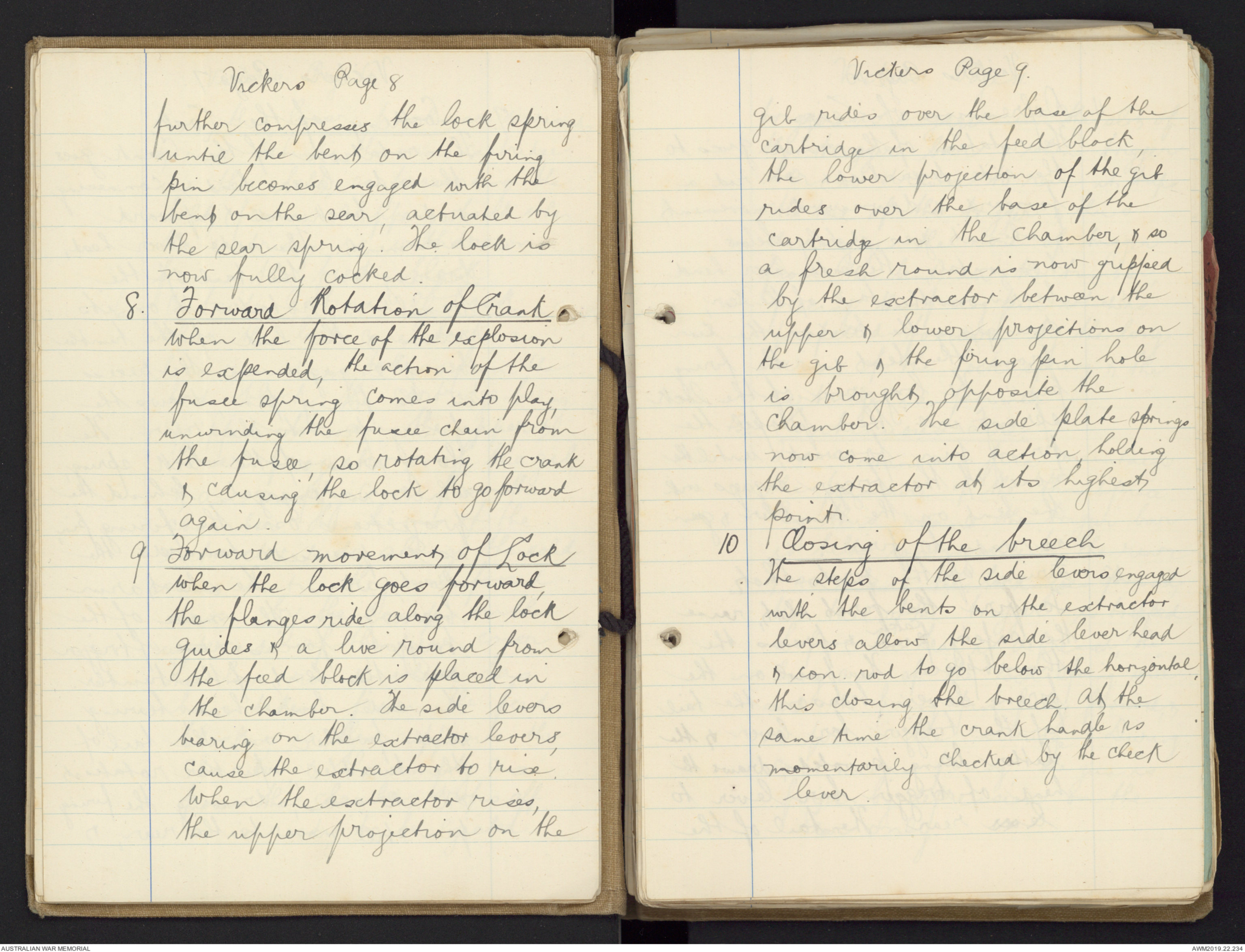
Vickers Page 8
further compresses the lock spring
until the bent on the firing
pin becomes engaged with the
bent on the sear, actuated by
the sear spring. The lock is
now fully cocked.
8. Forward Rotation of Crank
When the force of the explosion
is expended, the action of the
fusee spring comes into play,
unwinding the fusee chain from
the fusee, so rotating the crank
& causing the lock to go forward
again.
9 Forward movement of Lock
When the lock goes forward,
the flanges ride along the lock
guides & a live round from
the feed block is placed in
the chamber. The side levers
bearing on the extractor levers,
cause the extractor to rise.
When the extractor rises,
the upper projection on the
Vickers Page 9.
gib rides over the base of the
cartridge in the feed block,
the lower projection of the gib
rides over the base of the
cartridge in the chamber, & so
a fresh round is now gripped
by the extractor between the
upper & lower projections on
the gib & the firing pin hole
is brought opposite the
chamber. The side plate springs
now come into action, holding
the extractor at its highest
point.
10 Closing of the breech
The steps of the side levers engaged
with the bents on the extractor
levers allow the side lever head
& con. rod to go below the horizontal,
this closing the breech. At the
same time the crank handle is
momentarily checked by the check
lever.
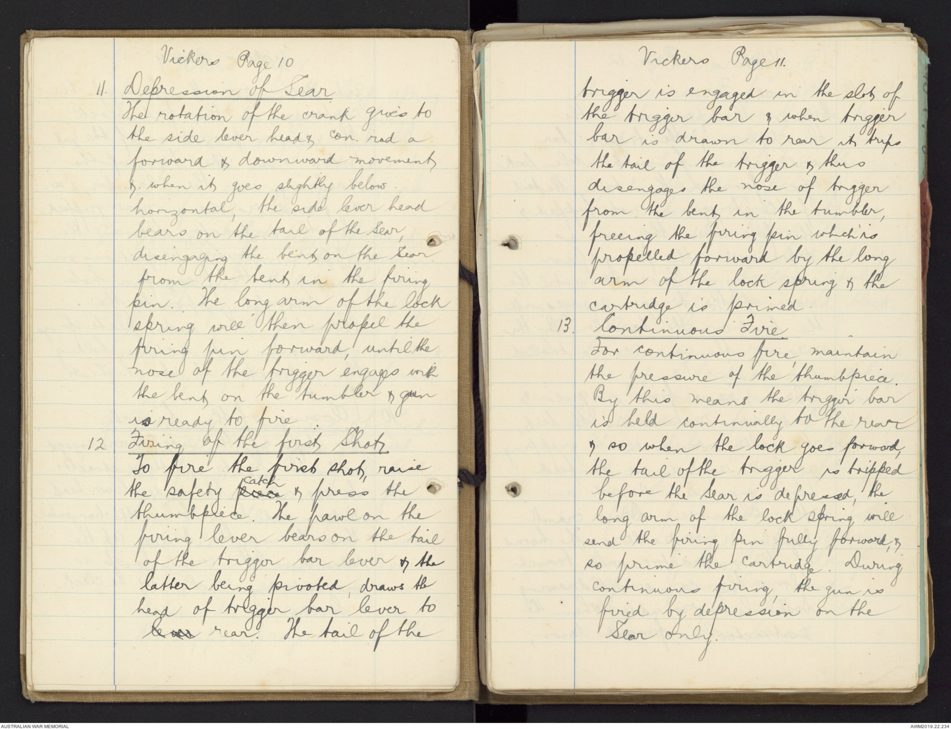
Vickers Page 10
11. Depression of Sear
The rotation of the crank gives to
the side lever head & con. rod a
forward & downward movement
& when it goes slightly below
horizontal, the side lever head
bears on the tail of the Sear,
disengaging the bent on the Sear
from the bent in the firing
pin. The long arm of the lock
spring will then propel the
firing pin forward, until the
nose of the trigger engages with
the bent on the tumbler & gun
is ready to fire.
12 Firing of the first Shot
To fire the first shot, raise
the safety piece catch & press the
thumbpiece. The pawl on the
firing lever bears on the tail
of the trigger bar lever & the
latter being pivoted, draws the
head of trigger bar lever tolever rear. The tail of the
Vickers Page 11.
trigger is engaged in the slot of
the trigger bar & when trigger
bar is drawn to rear it trips
the tail of the trigger & thus
disengages the nose of trigger
from the bent in the tumbler,
freeing the firing pin which is
propelled forward by the long
arm of the lock spring & the
cartridge is primed.
13. Continuous Fire.
For continuous fire, maintain
the pressure of the thumbpiece.
By this means the trigger bar
is held continually to the rear
& so when the lock goes forward,
the tail of the trigger is tripped
before the Sear is depressed, the
long arm of the lock spring will
send the firing pin fully forward, &
so prime the cartridge. During
continuous firing, the gun is
fired by depression on the
Sear only.
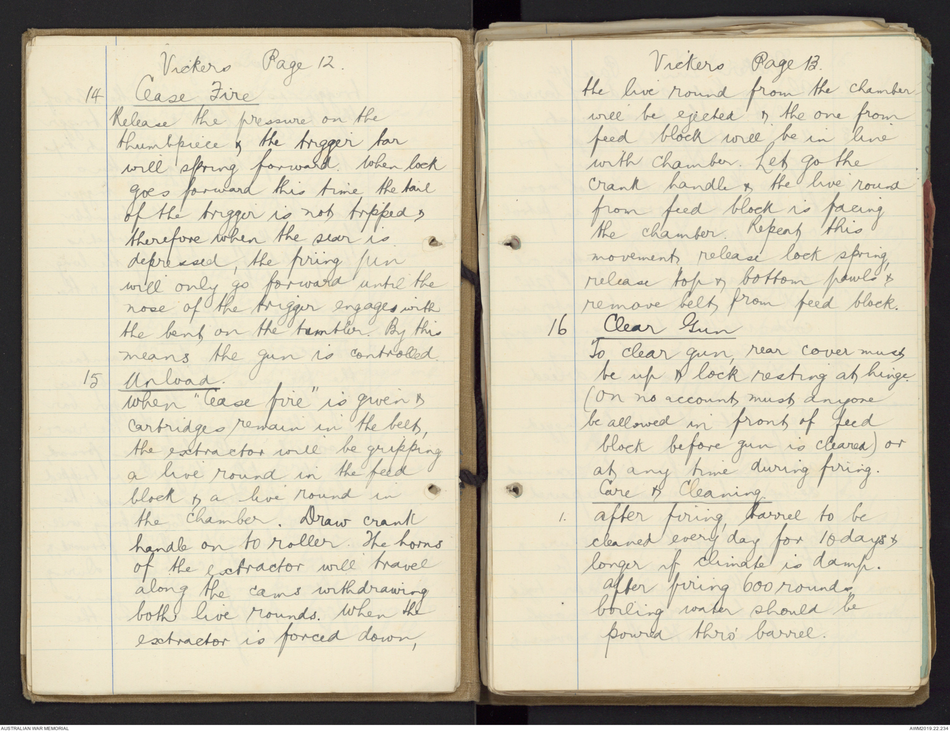
Vickers Page 12.
14 Cease Fire
Release the pressure on the
thumbpiece & the trigger bar
will spring forward. When lock
goes forward this time the tail
of the trigger is not tripped &
therefore when the sear is
depressed, the firing pin
will only go forward until the
nose of the trigger engages with
the bent on the tumbler. By this
means the gun is controlled.
15 Unload.
When "Cease fire" is given &
cartridges remain in the belt,
the extractor will be gripping
a live round in the feed
block & a live round in
the chamber. Draw crank
handle on to roller. The horns
of the extractor will travel
along the cams withdrawing
both live rounds. When the
extractor is forced down,
Vickers Page 13.
the live round from the chamber
will be ejected & the one from
feed block will be in line
with chamber. Let go the
crank handle & the live round
from feed block is facing
the chamber. Repeat this
movement, release lock spring,
release top & bottom pawls &
remove belt from feed block.
16 Clear Gun
To clear gun, rear cover must
be up & lock resting at hinge.
(on no account must anyone
be allowed in front of feed
block before gun is cleared) or
at any time during firing.
Care & Cleaning
1. After firing, barrel to be
cleaned every day for 10 days &
longer if climate is damp.
After firing 600 rounds
boiling water should be
poured thro' barrel.
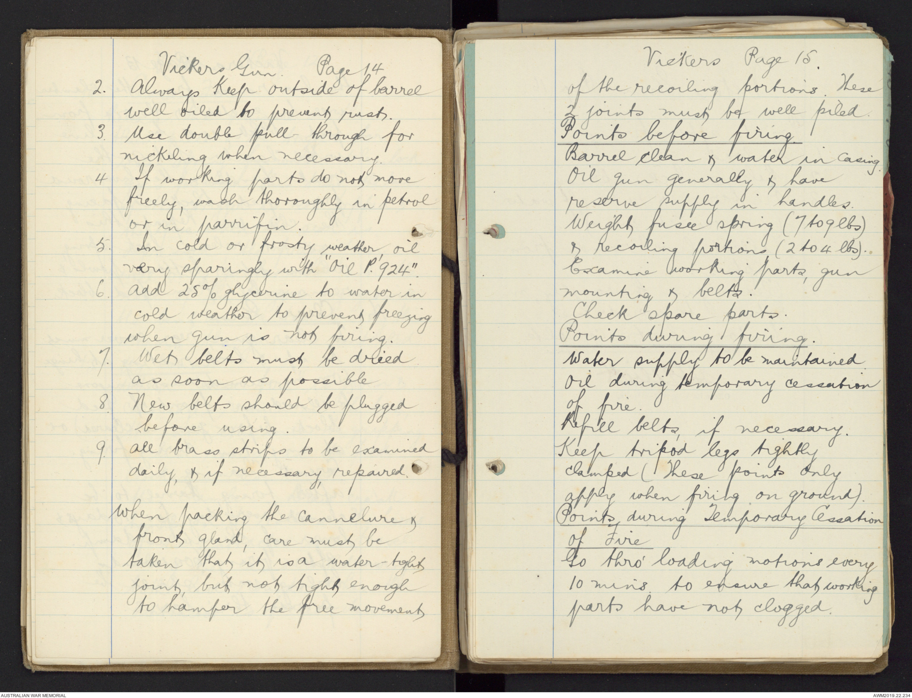
Vickers Gun. Page 14
2. Always keep outside of barrel
well oiled to prevent rust.
3. Use double pull-through for
nickeling when necessary.
4 If working parts do not move
freely, wash thoroughly in petrol
or in parrifin.
5. In cold or frosty weather, oil
very sparingly with "Oil P. 924".
6. Add 25% glycerine to water in
cold weather to prevent freezing
when gun is not firing.
7. Wet belts must be dried
as soon as possible
8. New belts should be plugged
before using.
9. All brass strips to be examined
daily, & if necessary, repaired.
When packing the cannelure &
front gland, care must be
taken that it is a water-tight
joint, but not tight enough
to hamper the free movement
Vickers Page 15.
of the recoiling portions. These
2 joints must be well piled.
Points before firing.
Barrel clean & water in casing.
Oil gun generally & have
reserve supply in handles.
Weight fusee spring (7 to 9lbs)
& recoiling portions (2 to 4lbs).
Examine working parts, gun
mounting & belts.
Check spare parts.
Points during firing.
Water supply to be maintained.
Oil during temporary cessation
of fire.
Refill belts, if necessary.
Keep tripod legs tightly
clamped (These points only
apply when firing on ground).
Points during Temporary Cessation
of Fire
Go thro' loading motions every
10 mins to ensure that working
parts have not clogged.
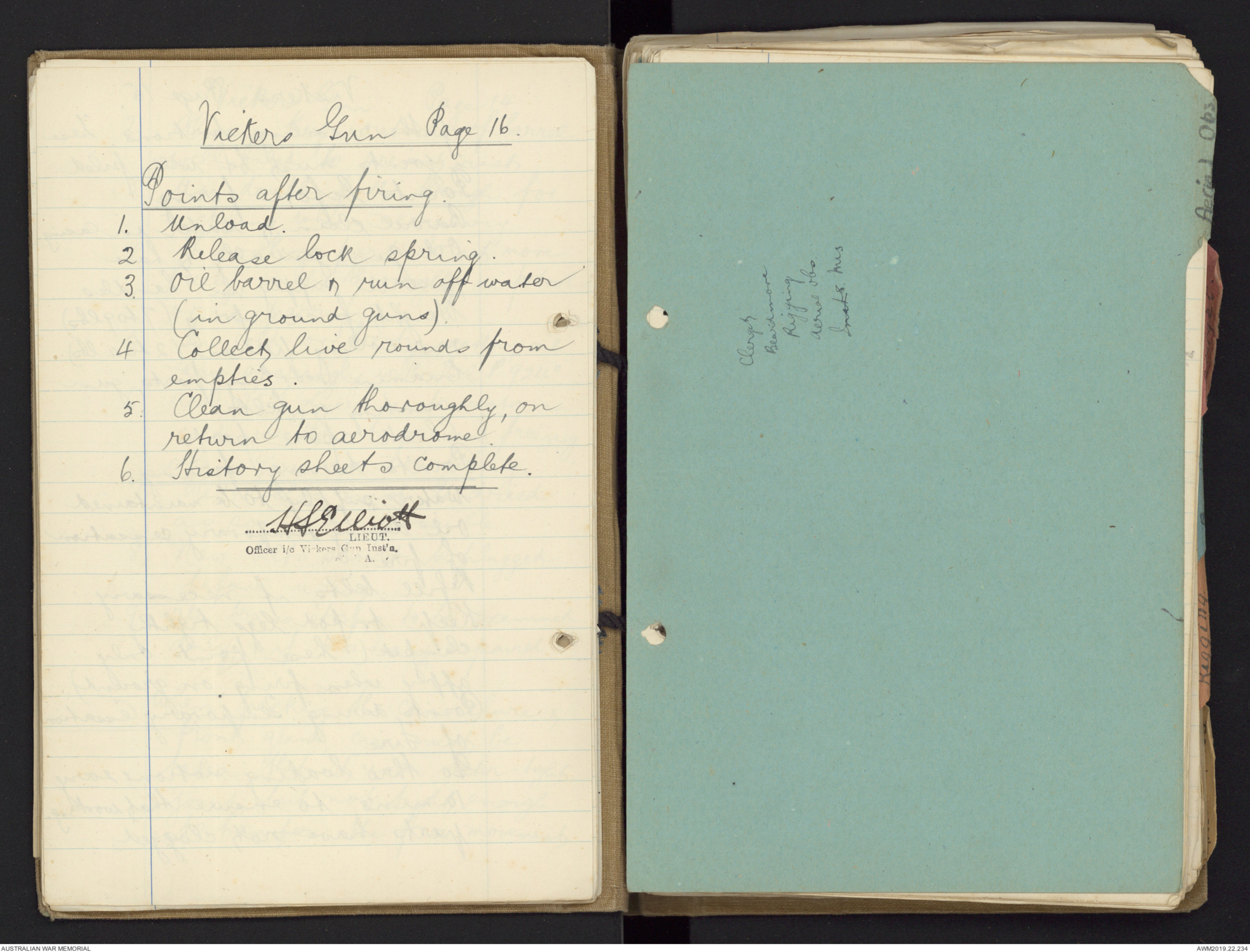
Vickers Gun Page 16.
Points after firing.
1. Unload.
2. Release lock spring.
3. Oil barrel & run off water
(in ground guns).
4 Collect live rounds from
empties.
5. Clean gun thoroughly, on
return to aerodrome.
6. History sheets complete.
HS Elliott
LIEUT.
Officer i/c Vickers Gun Inst'n
[[? A.]]
[*Clerget
Beardmore
Rigging
Aerial obs.Inats. Mis*]
[*Aerial Obs.*]
 Marisa Bortolotto
This transcription item is now locked to you for editing. To release the lock either Save your changes or Cancel.
This lock will be automatically released after 60 minutes of inactivity.